The STM32 Blue Pill is a popular platform for beginners who are getting started with STM32 Microcontrollers. It is very cheap and has support from ST (in terms of software, drivers, debuggers), Arduino (libraries), and PlatformIO. What if you want to take your STM32 experience to the next level? I found the STM32G4 series quite interesting. It is much more powerful than the Blue Pill and has a lot of peripherals. So, I decided to explore the STM32G4 and create a bunch of beginner-friendly guides. This is the Introduction to STM32G4.
You can think of it as a Getting Started with STM32G4 guide as I will take you through all the essentials of working with an STM32G4 MCU. If you are already familiar with STM32F103 MCU (the one in the Blue Pill), use this guide to familiarize yourself with a bigger and better microcontroller.
Even if you haven’t worked with any STM32 microcontrollers before, this guide will be helpful as I intend to make it as basic as possible. You will learn about the hardware, the development board (with STM32G431CBU6 MCU), how to set up the programming environment (STM32 Cube IDE, Arduino, and PlatformIO), and write your first STM32 program.
NOTE: This is a very lengthy and detailed guide on STM32G4. Use the Table of Contents to jump to the relevant section, if you want to. In case you are a beginner, I recommend you to go through the entire guide as I will discuss some of the basics and essential concepts you need to know.
NOTE: In this first “Introduction to STM32G4” guide, we will work exclusively with Arduino IDE. I will make two more similar and very-detailed guides on Getting Started with STM32G4 with STM32CubeIDE and PlatformIO.
A Brief Introduction to STM32G4 Series
You might already be familiar with the STM32F1 and STM32F4 series of Microcontrollers. The STM32G4 series is a relatively new lineup from STMicroelectronics (launched in 2019). They are a bunch of mixed-signal MCUs with a whole lot of analog and digital peripherals.
The ‘4’ in the name suggests that it uses an ARM Cortex-M4 CPU at its core. There is also a less powerful series in the form of STM32G0 (that uses ARM Cortex-M0 CPU core) but we will focus on the STM32G4 for this guide.
Further, we can divide the STM32G4 series into the following three sub-series:
- STM32G4x1: Entry-level Microcontrollers.
- STM32G4x3: Performance Series with focus on Analog peripherals.
- STM32G4x4: Hi-resolution MCUs with focus on hi-resolution timers, waveform builders, and other peripherals essential for digital power control.
At the time of writing this guide, there are about 80+ MCUs in the STM32G4 series and all of them run at a maximum clock speed of 170MHz.
STM32G4 Development Board (STM32G431 Core Board)
When I decided to work on the STM32G4 series, I started looking for development boards. There are the usual NUCLEO development boards from ST but I thought I needed something similar to the Blue Pill (both in terms of form factor and price).
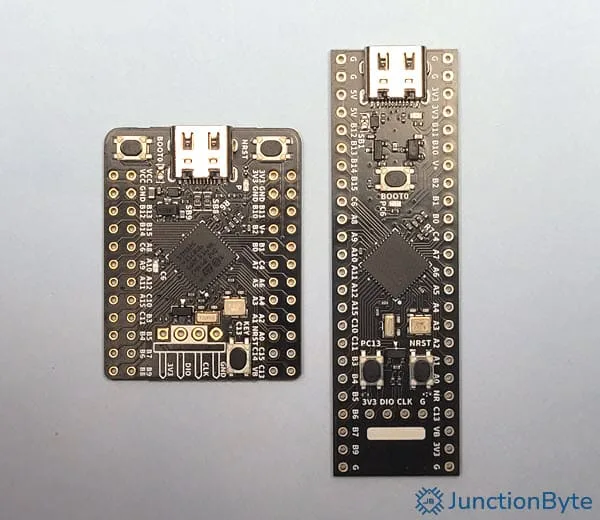
After some basic research, I stumbled upon the WeAct Studios STM32G431 Core Board. There are two versions of it: a regular one (similar to the Blue Pill) and a smaller board. I purchased both of them for ₹360 (about $4.2) each. You can get them for much less than this (depending on where you live). Apart from the difference in physical layout, both the boards are identical in terms of circuit design.
The microcontroller they used is the STM32G431CBU6. As I mentioned before, it uses an ARM Cortex-M4 CPU core with a clock speed of 170MHz, 32KB SRAM, and 128KB Flash. I’ll leave a link to the product page on ST’s website, where you can get all the documentation corresponding to this MCU (the important ones are the datasheet and reference manual).
If you are new to the world of ARM Microcontrollers, then here’s the hierarchy of documents (from low-level to high level) you need to follow:
- ARM Architecture Reference Manual
- ARM Core TRM (Technical Reference Manual)
- ARM Core User Manual
- MCU Manufacturer Reference Manual
- MCU Manufacturer Datasheet
STM32G431 Core Board Features
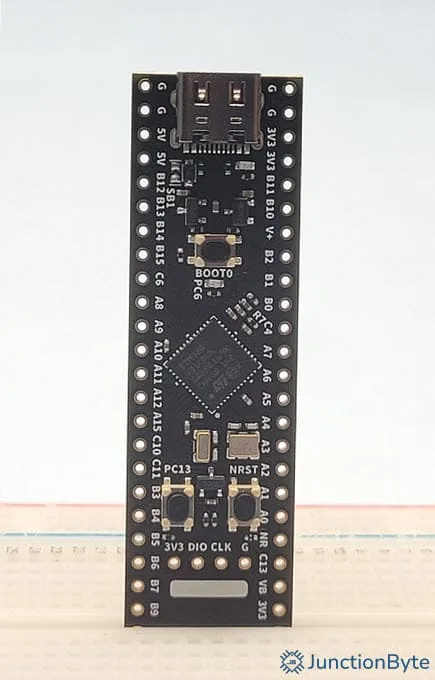
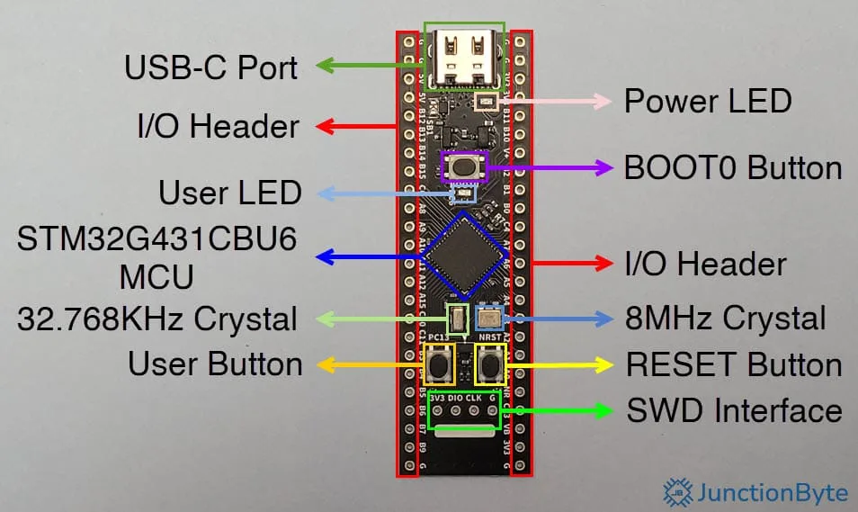
Apart from the STM32G431CBU6 MCU, STM32G431 Core Board has a USB-C Port for power as well as DFU Protocol. Both the long edges have 24 IO connection points (each) for soldering pin headers. The bottom short edge has connections for SWD (Serial Wire Debugger).
There are three push buttons on the board (BOOT0, RESET, and a User Button) and two LEDs (Power LED and User LED). For clock related hardware, the board has one 8MHz main crystal and one 32.768KHz crystal for RTC. The remaining components are for voltage regulation (5V to 3.3V) and a bunch of passives (decoupling caps, pull-down resistors for USB CC Lines, and other housekeeping.
Here’s a list of the important features of the STM32G431 Core Board, for your reference:
- The main MCU is STM32G431CBU6
- USB-C Port – For power and programming
- Reset Switch – To reset the Microcontroller
- BOOT Switch – To control the boot modes
- User Switch – You can use this switch in applications
- Power LED – Indicates power-on status
- User LED – You can use this LED in applications
- The main clock source is a 8MHz Crystal
- Has a 32.768KHz Crystal for RTC clock
- On-board 3.3V regulator
- SWD Interface – For programming and debugging through STLink
STM32G431 Core Board Pinout
The STM32G431 Core Board comes with unsoldered IO pins. You have to solder the headers so that you can connect all the analog and digital peripherals to these IO pins. The following image shows the pinout of the STM32G431 Core Board. At first, I thought of naming all the alternate functions of the IO pins in the pinout diagram. After going through a couple of pins, it occurred to me that the STM32G431CBU6 MCU is much more complicated (than, say, the STM32F103C8T6, which is on the Blue Pill) and each pin has a lot more functions.

So, I decided not to include the alternate functions of all the IO pins on the board. Whenever I use a particular pin for GPIO or other purposes, I will clearly mention all the possible functions that the pin supports. You will always have the datasheet from ST as a reference to get all the relevant information.
As you can see from the above pinout diagram, not all pins on the STM32G431 Core Board support 5V. This is very important if you want to connect different peripherals to the MCU. Keep an eye on the voltage ratings of the IO pins.
NOTE: I tried my best to make the pinout diagram as accurate as possible in terms of 5V tolerance and PWM capabilities. If you find any mistakes, do let me know so that I can verify them and make necessary changes. I also have the pinout project file in Canva. If anyone is interested in creating a complete pinout image with all the alternate functions of the IO pins, contact me.
How to Program the STM32G431 Core Board?
The advantage of some of the popular prototyping boards (Arduino, ESP8266 Node MCU, ESP32, and Raspberry Pi Pico) is that they are very easy to program. When I say program, I mean uploading the code to the MCU’s Flash. You don’t need any additional programming hardware with all these boards. All you have to do is connect them to a computer and hit the upload button (or drag-and-drop the binary file).
Official ST development boards for STM32 (Discovery and Nucleo are very popular) usually come with on-board ST-LINK hardware for programming and debugging. However, things are a little bit different when it comes to non-official STM32 boards. When you purchase Blue Pill or in this case the WeAct Studio STM32G431 Core Board, all you get is the microcontroller with access to its IO pins through pin headers and an easy way to power the device (through a USB Port).
To upload the code, you need an external ST-LINK Programmer Module and they are very cheap (possibly clones). However, there are two more alternatives in case of the STM32G431 Core Board that doesn’t require the ST-Link Hardware. One is using the USB DFU (Device Firmware Update) Protocol and the other is using a USB to UART Module (such as the FTDI 232 or other similar devices).
In either case, you have to use the combination of RESET and BOOT button on the development board. I will explain all the necessary steps when we upload the program later.
What Hardware Do You Need?
Let me talk about the hardware requirements for this introduction to the STM32G4 series. All you need is the STM32G431 Core Board (or other similar development boards) to start your journey with the STM32G4. You can get a slightly expensive Nucleo (NUCLEO-G474RE) board but for the purpose of this getting started with STM32G4 MCU series, I believe the STM32G431 Core Board is more than enough.
In addition to the main development board, you might need the following hardware:
- ST-LINK Programmer – For programming and debugging
- USB to UART Adapter or Module – For Programming and Serial Communication
Even if you don’t have these two accessories, you need not worry as I will show how to upload the program using just a USB-C Cable.
Getting Started with STM32G4 in Arduino
Let us begin with the easy stuff. The advantage of using powerful microcontrollers such as the STM32G431 with Arduino IDE is that the IDE takes away a lot of complexities (in terms of initial configuration) from the user and still sticks to the same old Arduino programming pattern. If you have knowledge on how to write decent Arduino programs, then you can use that skill to write code for STM32 MCUs as well. Some users like it, some don’t.
Preparing Arduino IDE
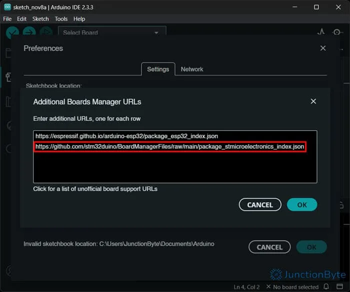
That said, setting up the Arduino IDE for STM32G4 is really simple. If you have the Arduino IDE installed on your computer, open it. Install it first, if you don’t. I am using the latest Arduino IDE version 2.3.3.
Open the Preferences Windows (File->Preferences) and paste the following link in the text field next to the “Additional boards manager URLs” option.
https://github.com/stm32duino/BoardManagerFiles/raw/main/package_stmicroelectronics_index.json
If you previously worked with the STM32 Blue Pill, then you don’t have to do anything as it is the same URL. You can add multiple such URLs by separating with commas. Alternatively, click the button on the right to the text field and add one URL per line.
What this does is it gives the Arduino IDE the ability to look for additional platforms (such as ESP32, STM32, etc.) and install the necessary board packages, libraries, and all the necessary tools for those platforms.
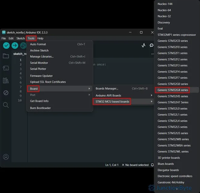
Now, open the Boards Manager in the Arduino IDE (Tools->Board->Boards Manager) and search for ‘STM32’ in the filter field. The top result must be ‘STM32 MCU based boards by STMicroelectronics’ and just click the install button.

Arduino IDE will now download and install all the necessary tools (GCC Compiler, CMSIS files, libraries, and other files) for STM32 MCUs.
Install STM32CubeProgrammer Software
While this process installs most of the necessary tools for using STM32 MCUs with Arduino IDE, there is one more software that we need to install manually. It is the STM32CubeProgrammer. This software is important if we want to upload the code to the MCU without any ST-LINK hardware (USB DFU or UART).
I’ll provide a link to the download page of the STM32CubeProgrammer. You need to have an account with ST in order to download this software (or any other SM32 software for that matter). After downloading the zip file, extract it and run the executable. The installation process is pretty straightforward but the important thing is to ensure that the installation directory is the default, which is “C:\Program Files\STMicroelectronics\STM32Cube\STM32CubeProgrammer” in case of a 64-bit Windows OS.
We will not use this software directly (at least when using Arduino IDE).
Write a Sketch in Arduino IDE
We are now ready to write our first program for the STM32G431 Core Board in Arduino IDE. Open the IDE and create a new sketch (File->New Sketch).
As I mentioned in the STM32G4 Core Board Pinout section, the board comes with one user LED and it is connected to PC6 (Pin 6 of GPIO Port C). It is an active HIGH LED i.e., when the pin is HIGH, the LED will be ON and when the pin is LOW, it will be OFF.
Here’s a simple LED Blinky Sketch to blink the on-board LED of the STM32G431 Core Board.
void setup()
{
  pinMode(PC6, OUTPUT); // Initialize the Pin PC6 as an Output.
}
void loop()
{
  digitalWrite(PC6, HIGH);  // Turn the LED ON
  delay(1000);              // Wait for a second
  digitalWrite(PC6, LOW);   // Turn the LED OFF
  delay(1000);              // Wait for a second
}
Before uploading the code, we have to select the proper board in the Arduino IDE and make some changes to the upload settings.
Select STM32G4 Board in Arduino IDE
In the Arduino IDE set the main series by going to Tools->Boards->STM32 MCU based boards->Generic STM32G4 series. After this, you will now see some new options in the ‘Tools’ menu. You can leave most of these options in their default state except for two.
First we have to select the actual MCU in the STM32G4 series. We know that the MCU on the STM32G431 Core Board is STM32G431CBU6. So, to go Tools->Board part number and select the “Generic G431CBUx” MCU.
Next, the upload method. Go to Tools->Upload method and select the “STM32CubeProgrammer (DFU)” option.
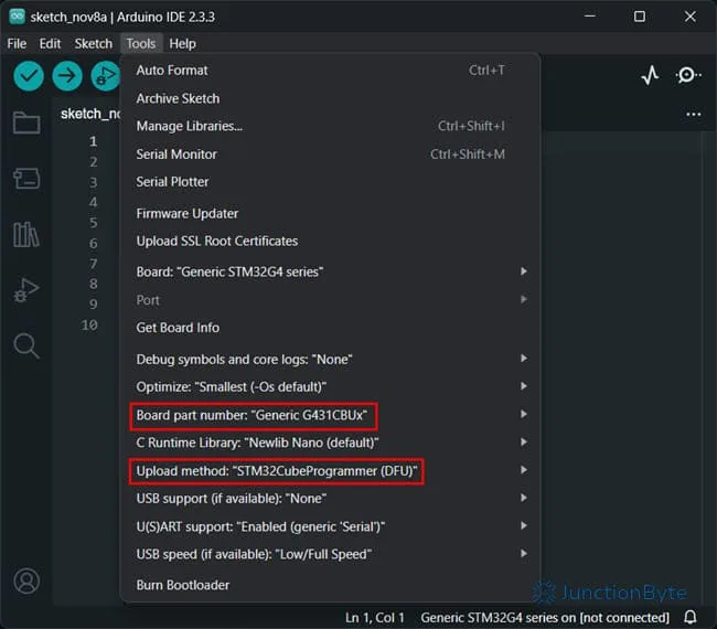
As you can see from the options, all the upload methods are directly associated with STM32CubeProgrammer and that is why we had to install this software.
Importance of BOOT Modes and BOOT0 Button
When you power on the STM32G431 Core Board (or any modern STM32 Microcontrollers for that matter), the system can boot from any of the following three memory/storage options:
- Flash
- System Memory
- Embedded SRAM
Of these three, the first two i.e., Flash and System Memory are important for us. The ‘Flash’ memory contains the regular application code while the ‘System Memory’ consists of a bootloader program that can reprogram the Flash memory using UART, I2C, SPI, and USB DFU.
We can select how the system boots by controlling the PB0-BOOT0 pin of the microcontroller. When this pin is LOW during startup (i.e., while powering on the MCU), the system boots from the Flash memory and runs the user application code.
However, if the PB0-BOOT0 is HIGH during startup, the system boots from the System Memory and we can reprogram the Flash memory with new application code.
On the STM32G431 Core Board, the BOOT0 is connected to the PB0-BOOT0 pin of the MCU, which is normally pulled LOW. When we push the BOOT0 button while powering the board on, we can essentially set the MCU in “programming” mode or ISP (In-system Programming) mode.
Interested in an affordable Spot Welding Machine? Check out the review of FNIRSI SWM-10 Spot Welder for 18650 Batteries.
How to Enter ISP Mode on STM32G431 Core Board?
There are a couple of ways to activate the ISP mode on the STM32G431 Core Board.
If the board is powered off, press and hold the BOOT0 button while plugging in the USB Cable.
Alternatively, if the board is already powered on i.e., the USB-C cable is plugged into the computer, press and hold both the RESET and BOOT0 buttons simultaneously. First release the RESET button and after 1s, release the BOOT0 button.
You should see a new entity in the ‘Device Manager’ as “DFU in FS Mode” under the ‘Universal Serial Bus devices’ category.
Install DFU Drivers
If you don’t see the DFU device in the Device Manager, chances are, your system is missing the DFU drivers. So, let me tell you how to install the drivers now.
Open the folder where the STM32CubeProgrammer is installed i.e., “C:\Program Files\STMicroelectronics\STM32Cube\STM32CubeProgrammer.”
Then navigate to Drivers->DFU_Driver and double click the “STM32Bootloader.bat” file. You might have to restart the device or re-plug the device, depending on your system (usually, not necessary).
If you cannot see the DFU device even after installing drivers, make sure that the USB-C cable you are using supports data transfer. You can also flip the USB-C connector and reconnect the cable.
Upload the Code to STM32G431 Core Board in Arduino IDE
We are coming to the final act of this guide. You can see the Arduino IDE displaying “Generic STM32G4 series on [not connected]” at the bottom right. Sadly, this won’t change even when you put the board in ISP mode.
Speaking of which, in order to upload the program to the STM32G431 Core Board, you have to place it in ISP mode using either of the two methods that I previously mentioned.
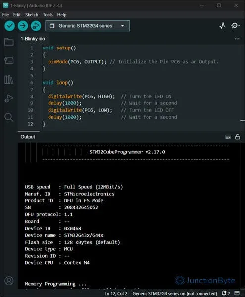
After this, you can click on the ‘Upload’ button in the Arduino IDE and if everything goes well, the Arduino IDE will compile the code, invoke the STM32CubeProgrammer, and upload the code to the STM32G431 Core Board.
Conclusion
This is the first guide in the STM32G4 Series where I gave an introduction to the STM32G4 microcontrollers, the development board (WeAct Studio’s STM32G431 Core Board), configuring Arduino IDE, installing necessary software and drivers, entering ISP mode, and finally, uploading a basic Blinky program.
If you followed all these steps and were able to successfully upload the code, it means all the configurations that you did worked without any issues. You can continue using Arduino IDE and develop all kinds of applications with the STM32G431 Core Board.
In the next set of guides, I will show the configuration steps with slightly advanced tools (STM32CubeIDE and PlatformIO). They will essentially be the Getting Started with STM32G4 guides for those respective platforms.
If you have any queries, comments, suggestions, or anything else, do let me know through the comments section.
Hi junctionbyte.com administrator, Your posts are always well presented.
Thankyou.
As you can see, I just started the ‘JunctionByte’ journey and hope to get better everyday.
To the junctionbyte.com owner, Your posts are always well researched.
Thankyou.
Sir, this was a nicely written introduction. A couple of suggestions for your audience. You appropriately mentioned the STM32CubeProgrammer tool. As of this writing, it is at version 2.19. In addition to programming the target micro, you may also use it to observe the option bytes to check out the configuration including the BOOT situation. Equally important, you may peek and poke registers at the bit level which can greatly aid development and troubleshooting. The other fantastic tool is the STM32CubeMx. This is a GUI environment that aids in the configuration of the micro. It will provide machine generated code for all the peripherals, direct the clock tree, organize the DMA scheme, and sort out interrupt priorities. there are a ton of simple firmware projects available to help the designer to get used to using the STM32G4xx. Keep up the good work!
Hi Jeff,
Thankyou for the appreciative words. You are right. The STM32CubeProgrammer is an interesting tool. As I intended this guide to be “beginner centric,” I did not cover all the features of the tool. I may revisit this sometime in the future and elaborate all of its capabilities.
Regarding the STM32CubeMX, I made a separate guide (that focuses on PlatformIO), where I explained how to use the STM32CubeMX to configure the device, its pins, clock, and generate a basic “starting” code. I also covered the STM32CubeIDE in a dedicated guide (just the project creation and compilation, not anything advanced).