The 16×2 Alphanumeric Character LCD (or 1602 LCD) is one of the most popular display modules in the world of embedded systems. DIYers, hobbyists, and engineers working with microcontrollers often use this LCD to display simple text messages and numbers, sensor data, date and time, or any alphanumeric information. In this guide, I will explain everything you need to know about interfacing a 16×2 LCD with an 8051 Microcontroller.
You might have used a 1602 LCD Module with Arduino or Raspberry Pi. The advantage of those platforms is you get ready-to-use libraries. All you need to do is import those libraries and use them in your applications.
When it comes to the 8051 Microcontroller, things aren’t that straightforward. For starters, you don’t have any standard libraries to interface a 16×2 LCD. So, in this guide, we will see how to write a driver (library) for a 16×2 LCD for the 8051 Microcontroller Platform from scratch.
IMPORTANT NOTE: I already wrote the basic GPIO Driver for 8051 Microcontroller (specifically, the AT89S52 MCU). I will be using that driver as a base and develop the 16×2 LCD Driver. So, it is important to understand that library first before proceeding further. You can get more explanation about GPIO Driver for 8051 Microcontroller in the ‘Interfacing LED with 8051 Microcontroller’ guide.
A Brief Note on LCDs
Liquid Crystal Displays (LCDs) are widely-used display devices, thanks to their ability to produce clear, energy-efficient images. LCDs rely on liquid crystals to manipulate light and generate images.
LCDs generally fall into two main categories: character LCDs and graphic LCDs. Character LCDs display text in a grid of characters, where each character takes up a fixed area of the screen. These displays are straightforward to use and are best suited for simple text output. You can easily interface them with microcontrollers with fewer resources (pins, memory, etc.).
Graphic LCDs, on the other hand, can display more complex images and graphics. They have a grid of pixels that we can individually control to display graphics, images, and complex patterns. While these displays are more versatile, they require more processing power and memory to operate.
What is a 16×2 LCD?
A 16×2 LCD is a type of Character LCD screen that can display 16 characters per row and has 2 rows. With this configuration, it can display a total of 32 characters simultaneously.
Each character occupies a specific rectangular block with a grid of pixels, neatly arranged in a two-row format. The ‘5 x 8’ pixel grid/matrix is standard for most alphanumeric characters.
The ‘16×2’ or ‘1602’ label represents the size of the display, where the number 16 indicates the number of columns (characters) in each row, and the number 2 represents the rows. These 16×2 LCDs usually come with a backlight that improves the visibility in low-light conditions.
The heart of most 16×2 LCDs is the Hitachi HD44780 LCD controller. It manages all the operations of the LCD such as controlling the pixels on the screen, determining which characters appear, and more.
This controller acts as a bridge between the microcontroller and the display. It interprets the instructions from the microcontroller, processes them, and then displays the corresponding characters on the LCD.
16×2 LCD Pin Diagram and Pin Description
Pinout Diagram
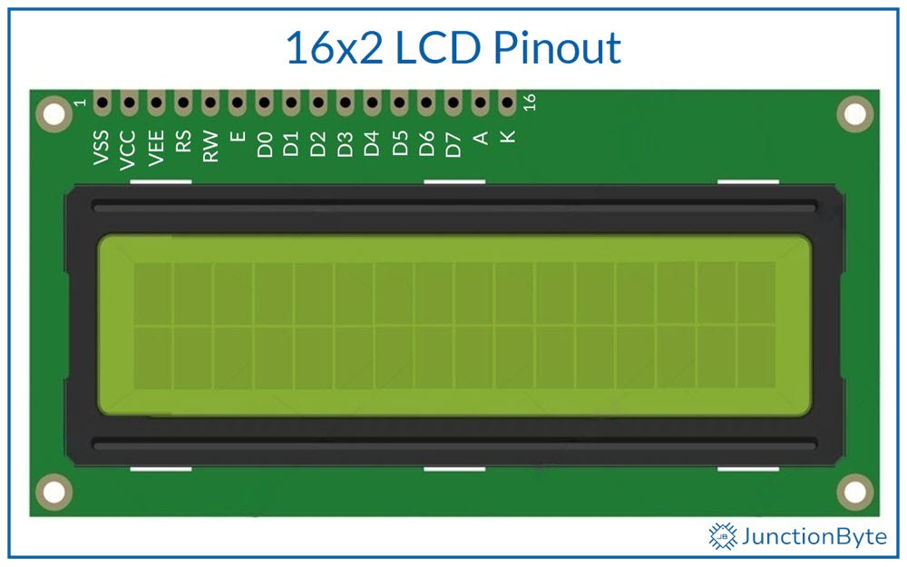
The 1602 LCD is available in a 16-Pin Module. Here is an image showcasing the 16×2 LCD Pin Diagram.
Pin Description
Let us now understand the Pins of a typical 16×2 LCD. The following table lists out all the Pins of 1602 LCD along with a brief description.
| Pin Number | Pin Name | Description |
| 1 | VSS | Ground Pin |
| 2 | VCC | Power Pin |
| 3 | VEE (V0) | Contrast Control |
| 4 | RS | Register Select |
| 5 | RW | Read / Write |
| 6 | E | Enable |
| 7 — 14 | D0 — D7 | Data Pins |
| 15 | A (LED+) | Anode of Backlight LED |
| 16 | K (LED-) | Cathode of Backlight LED |
Function of Each Pin
Let us understand the role of each pin on the 16×2 LCD. This is important for connecting the display to a microcontroller or other control unit.
- Power Supply (VSS, VCC): VSS (Pin 1) is the ground pin, connecting the negative side of the power supply (GND). VCC (Pin 2) connects to the positive side, usually +5V.
- Contrast Control (VEE or V0): The VEE or V0 (Pin 3) adjusts the contrast of the LCD. We have to connect this pin to a potentiometer. It allows us to change the contrast of the LCD by adjusting the voltage level sent to this pin. It accepts analog voltage between 0V and +5V. Contrast is inversely proportional to the voltage on this pin.
- The next three pins (RS, RW, E) are crucial for determining how the LCD interprets incoming data.
- Register Select (RS): The RS pin (Pin 4) controls whether the LCD is in command or data mode. It determines whether the data present on the D0-D7 is command data or character data.
- RS = 0, LCD expects a command on D0-D7.
- RS = 1, LCD expects character data on D0-D7.
- Read/Write (RW): The RW pin (Pin 5) allows you to switch between read and write modes. It controls whether data is read from or written to the LCD.
- RW = 0, write data to the LCD.
- RW = 1, read data from the LCD.
- Enable (E): The E pin (Pin 6) allows data to be latched from the data pins (D0-D7) to corresponding registers. A short high-to-low pulse (with a minimum duration of 450ns) on this pin signals the LCD controller to read or write the data.
- Data Lines (D0-D7): These are the data pins. The eight data pins (Pins 7-14) carry information to and from the microcontroller. In 8-bit mode, we need all eight data pins to send 8 bits of data at a time. In 4-bit mode, only four of these pins (D4-D7) are sufficient to send data in chunks of 4 bits and help save microcontroller pins.
- LED Backlight Control (A, K): The A or LED+ pin (Pin 15) is the anode for the backlight, and K or LED- pin (Pin 16) is the cathode. Connect anode to +5V and cathode to GND to enable LED backlight of the display. If you don’t need the backlight, leave these pins unconnected.
Understanding the Hitachi HD44780 LCD Controller
As I said before, the Hitachi HD44780 LCD controller is responsible for all the operations of character-based LCD modules like the 16×2 LCD.
Registers in the Controller
The HD44780 controller uses two primary 8-bit registers: the Data Register (DR) and the Command Register (IR).
The Data Register handles character data, which appears on the screen as text. We have to write ASCII codes or custom character data into this register to display text.
The Command Register manages instructions that control the display’s behavior. Commands like turning the display on or off, configuring the cursor, or setting the display mode are sent to this register.
Using the RS (Register Select) pin, we have to specify whether we are accessing the Data Register or the Command Register during operation.
Data Transfer Modes
The controller supports two modes of data transfer: 4-bit and 8-bit modes. The 8-bit mode uses all eight data lines (D0 to D7) for faster data transfer. In contrast, the 4-bit mode only uses four data lines (D4 to D7). Engineers and developers often choose the 4-bit mode for projects with limited GPIO pins.
Character Generation
The HD44780 controller includes a Character Generator ROM (CGROM) and a Character Generator RAM (CGRAM).
The CGROM contains predefined character patterns for a wide range of standard characters, including letters, numbers, and symbols. These characters follow the ASCII standard, making them universally recognizable and easy to use.
When we send ASCII Data to the LCD, the controller compares the received data with the data in the CGROM and then fires appropriate segments on the display.
The CGRAM has a capacity of 64 Bytes. It allows us to define up to eight custom characters (8 Bytes per character) by specifying their pixel patterns.
We know that each character consists of a 5×8 pixel grid. By programming the binary values of this matrix in our application, we can store the special character pattern in the CGRAM.
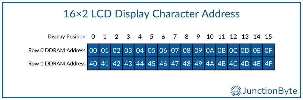
Apart from these two, there is the Display Data RAM (DDRAM). It corresponds to each display position on the LCD. It holds the 8-bit data corresponding to each character on the screen. For instance, the first character in the top row corresponds to address 0x00, while the first character in the second row corresponds to 0x40.
The following image shows the DDRAM addresses for all the display positions on a 16×2 LCD.
In case you want to use a 20×4 LCD, then here are the DDRAM Addresses for all the characters in four rows.
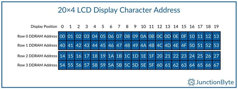
With appropriate command and the DDRAM address, you can display a character at any of the 32 locations.
Timing Considerations
The HD44780 controller operates efficiently when we follow specific timing guidelines. Commands require precise delays for proper execution. The datasheet of HD44780 mentions the necessary time required for execution of the commands.
I’ll specify the execution time of commands when we look at them later.
HD44780 Instruction Set
The following table has the instruction set for the HD44780 LCD Controller.
| Instruction | RS | RW | D7 | D6 | D5 | D4 | D3 | D2 | D1 | D0 |
| Clear Display | 0 | 0 | 0 | 0 | 0 | 0 | 0 | 0 | 0 | 1 |
| Return Home | 0 | 0 | 0 | 0 | 0 | 0 | 0 | 0 | 1 | — |
| Entry Mode Set | 0 | 0 | 0 | 0 | 0 | 0 | 0 | 1 | I/D | S |
| Display ON/OFF Control | 0 | 0 | 0 | 0 | 0 | 0 | 1 | D | C | B |
| Cursor or Display Shift | 0 | 0 | 0 | 0 | 0 | 1 | S/C | R/L | — | — |
| Function Set | 0 | 0 | 0 | 0 | 1 | DL | N | F | — | — |
| Set CGRAM Address | 0 | 0 | 0 | 1 | ACG | ACG | ACG | ACG | ACG | ACG |
| Set DDRAM Address | 0 | 0 | 1 | ADD | ADD | ADD | ADD | ADD | ADD | ADD |
| Read Busy Flag & Address | 0 | 1 | BF | AC | AC | AC | AC | AC | AC | AC |
| Write Data to CG or DDRAM | 1 | 0 | Write Data | |||||||
| Read Data from CG or DDRAM | 1 | 0 | Read Data | |||||||
- I/D = 1; Increment
- I/D = 0; Decrement
- S = 1; Accompanies Display Shift
- S/C = 1; Display Shift
- S/C = 0; Cursor Move
- R/L = 1; Shift Right
- R/L = 0; Shift Left
- DL = 1; 8-Bit Mode
- DL = 0; 4-Bit Mode
- N = 1; 2 Lines
- N = 0; 1 Line
- F = 1; 5 x 10 Dots
- F = 0; 5 x 8 Dots
- BF = 1; Busy
- BF = 0; Can accept instructions
- ACG: CGRAM Address
- ADD: DDRAM Address
- AC: Address Counter
Instruction Description and Execution Time
| Instruction | Description | Execution Time |
| Clear Display | Clears all display data (DDRAM) and sets DDRAM Address to 00H (cursor moves to the first block). | 1.52 – 1.65 ms |
| Return Home | Sets DDRAM Address to 00H (cursor moves to the first block). Contents of DDRAM remain the same. | 1.52 – 1.65 ms |
| Entry Mode Set | Sets cursor move direction and specifies display shift. I/D = 1, cursor/blink moves to right and DDRAM address is increased by 1. I/D = 0, cursor/blink moves to left and DDRAM address is decreased by 1. I/D = 1 and S = 1, Shift the display to the left. I/D = 0 and S = 1, Shift the display to the right. | 37 – 40 µs |
| Display ON/OFF | Controls display/cursor/blink ON/OFF. D = 1, Turn ON display. D = 0, Turn OFF display (display data is still in DDRAM) C = 1, Turn ON cursor. C = 0, Turn OFF cursor. B = 1, Turn ON cursor blink. B = 0, Turn OFF cursor blink. | 37 – 40 µs |
| Cursor or Display Shift | Shift cursor position or display. S/C = 0, R/L = 0, Shift cursor to left. S/C = 0, R/L = 1, Shift cursor to right. S/C = 1, R/L = 0, Shift display and cursor to left. S/C = 1, R/L = 1, Shift display and cursor to right. | 37 – 40 µs |
| Function Set | Sets interface data length, number of display lines, and character font. DL = 1, 8-bit bus mode. DL = 0, 4-bit bus mode. N = 0, 1-line display mode. N = 1, 2-line display mode. F = 0, 5 x 8 dots. F = 0, 5 x 11 dots. | 37 – 40 µs |
| Set CGRAM address | Set CGRAM address to access CGRAM data. | 37 – 40 µs |
| Set DDRAM address | Set DDRAM address to access DDRAM data. | 37 – 40 µs |
| Read busy flag & address | If BF is 1, the internal operation is in progress. The next instruction will not be accepted until BF is reset to 0. | 0 µs |
| Write data to CG or DDRAM | Write binary 8-bit data to DDRAM/CGRAM. | 40 – 43 µs |
| Read data to CG or DDRAM | Read binary 8-bit data from DDRAM/CGRAM | 40 – 43 µs |
16×2 LCD Commands
Understanding and decoding these instructions is difficult for beginners. So, I listed some of the commonly-used instructions for the HD44780 LCD Controller along with the instruction code. In the context of a 16×2 LCD, we usually call these commands. So, the following table consists of some of the popular 16×2 LCD Commands.
| Command | Code |
| Clear Display | 0x01 |
| Return Home | 0x02 |
| Set Entry Mode (with auto-increment) | 0x06 |
| Display ON, Cursor OFF | 0x0C |
| Display ON, Cursor ON | 0x0D |
| Display ON, Cursor Blink | 0x0E |
| LCD 8-Bit Mode (2-Lines, 5×8 Dots) | 0x38 |
| LCD 4-Bit Mode (2-Lines, 5×8 Dots) | 0x28 |
| Shift Display to Left | 0x18 |
| Shift Display to Right | 0x1C |
| Shift Cursor to Left | 0x10 |
| Shift Cursor to Right | 0x14 |
| Set Cursor to beginning of 1st Line | 0x80 |
| Set Cursor to beginning of 2nd Line | 0xC0 |
You can use these commands in the application directly to achieve the necessary operation.
4-bit vs. 8-bit Data Transfer Modes
The 16×2 (1602) LCD supports two modes for data communication: 4-bit and 8-bit modes.
In 8-bit mode, the microcontroller uses all eight data lines (D0-D7) of the LCD for communication. This mode has faster data transfer since all bits of a command or data byte are sent simultaneously. However, 8-bit mode needs more GPIO pins from the microcontroller (8 to be specific).
The 4-bit mode reduces the number of data lines needed by using only the higher nibble (D4-D7). In this mode, the microcontroller sends each command or data byte in two steps: first the higher nibble and then the lower nibble.
While 4-bit mode requires additional software processing to split the data, it significantly reduces the pin count. The trade-off is a slightly slower communication speed, which may not impact most applications that do not require rapid updates.
Circuit Diagram for Interfacing 16×2 LCD with 8051 Microcontroller
With all the theory aside, we are ready to connect a generic 16×2 LCD with a 8051 Microcontroller. First, let us see all the components you might need to successfully implement the project.
Components Needed
- 8051 Microcontroller Development Board
- 16×2 LCD Module (1602 LCD)
- 10KΩ Potentiometer
- Breadboard and Jumper Wires
NOTE: I am assuming that the 8051 Microcontroller Development Board has all the necessary components for the 8051 Microcontroller to boot. This includes the power supply, clock, reset, EA Pin pulled HIGH, etc. In case you don’t have these essential circuit components, you might need to add them in the list as well.
Circuit Diagram
The image shows the circuit diagram for interfacing a 16×2 LCD with 8051 Microcontroller.
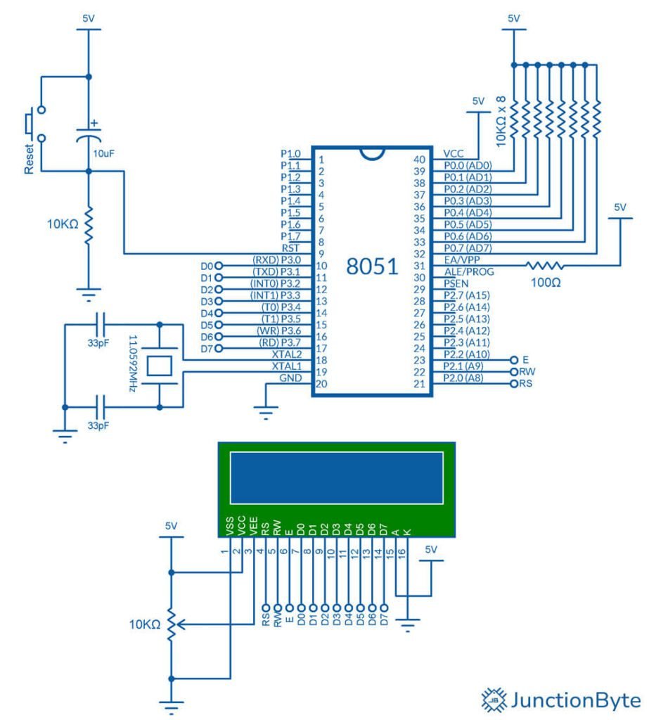
As you can see, I connected all the 8 data pins of the LCD to the 8051 Microcontroller. However, depending on the mode of operation, you can adjust the number of data lines you need.
Code for Interfacing 16×2 LCD with 8051 Microcontroller
If you just want to connect a 1602 LCD with an 8051 Microcontroller and display some data, then here is a simple and straightforward code for you. I added a lot of comments in the code for you to understand.
/*Include 8051 specific header file*/
#include <reg52.h>

/*Define control pins for the LCD*/

/*Assuming data pins D0 to D7 are connected to Port 3*/
#define LCD_PORT P3

sbit RS = P2^0  /*Register Select pin connected to P2.0*/
sbit RW = P2^1  /*Read/Write pin connected to P2.1*/
sbit EN = P2^2  /*Enable pin connected to P2.2*/

/*Function prototypes*/
void delay_ms(unsigned int ms);
void LCD_Command(unsigned char cmd);
void LCD_Data(unsigned char data);
void LCD_Init(void);
void LCD_Clear(void);
void LCD_GoTo(unsigned char row, unsigned char col);
void LCD_String(char *str);
bit LCD_Busy(void);

/*Main Function*/
void main(void)
{
  LCD_Init();       /*Initialize the LCD*/
  LCD_Clear();      /*Clear the LCD screen*/

  LCD_GoTo(1, 3);   /*Move cursor to row 1, column 3*/
  LCD_String("JunctionByte");  /*Display string "JunctionByte"*/

  LCD_GoTo(2, 6);   /*Move cursor to row 2, column 6*/
  LCD_String("Hello");  /*Display string "Hello"*/

  while(1);          /*Infinite loop to keep the program running*/
}

/*Delay function (1 ms approx) for 8051 microcontroller*/
void delay_ms(unsigned int ms)
{
  unsigned int i, j;
  for(i = 0; i < ms; i++)
  {
    for(j = 0; j < 1275; j++);
  }
}

/*Function to check the busy flag of the LCD*/
bit LCD_Busy(void)
{
  bit busyFlag;

  /*Set RW pin to read mode*/
  RW = 1;
  RS = 0;      /*Command mode*/
  EN = 1;      /*Enable pin high to latch data*/

  /*Small delay to ensure LCD has time to output the busy flag*/
  delay_ms(1);

  /*Check if the 7th bit is high (Busy flag)*/
  busyFlag = LCD_PORT & 0x80;

  EN = 0;  /*Disable the LCD after reading the busy flag*/
  return busyFlag;
}

/*Function to send a command to the LCD*/
void LCD_Command(unsigned char cmd)
{
  while(LCD_Busy());  /*Wait until LCD is not busy*/

  RS = 0;             /*Command mode*/
  RW = 0;             /*Write mode*/
  LCD_PORT = cmd;     /*Send command*/
  EN = 1;             /*Enable pulse*/
  delay_ms(1);        /*Wait for LCD processing*/
  EN = 0;             /*Disable LCD*/
}

/*Function to send data to the LCD*/
void LCD_Data(unsigned char data)
{
  while(LCD_Busy());  /*Wait until LCD is not busy*/

  RS = 1;             /*Data mode*/
  RW = 0;             /*Write mode*/
  LCD_PORT = data;    /*Send data*/
  EN = 1;             /*Enable pulse*/
  delay_ms(1);        /*Wait for LCD processing*/
  EN = 0;             /*Disable LCD*/
}

/*Function to initialize the LCD*/
void LCD_Init(void)
{
  delay_ms(15);         /*Wait for LCD to power up*/
  LCD_Command(0x38);    /*8-bit mode, 2 lines, 5x8 font*/
  LCD_Command(0x0C);    /*Display on, cursor off*/
  LCD_Command(0x06);    /*Auto-increment cursor*/
  LCD_Command(0x01);    /*Clear display*/
  delay_ms(2);          /*Wait for clear operation*/
}

/*Function to clear the LCD screen*/
void LCD_Clear(void)
{
  LCD_Command(0x01);    /*Clear display command*/
  delay_ms(2);          /*Wait for clear to finish*/
}

/*Function to move the cursor to a specific position*/
void LCD_GoTo(unsigned char row, unsigned char col)
{
  unsigned char position;

  if (row == 1)
  {
    position = 0x80 + col;  /*First row*/
  }
  else if (row == 2)
  {
    position = 0xC0 + col;  /*Second row*/
  }

  LCD_Command(position);  /*Set cursor position*/
}

/*Function to display a string on the LCD*/
void LCD_String(char *str)
{
  while (*str)
  {
    LCD_Data(*str);  /*Send each character to the LCD*/
    str++;
  }
}

How to Create Custom Characters in 16×2 LCD?
Before looking at the 16×2 Driver for 8051 Microcontroller, I want to discuss one of the popular features of 1602 LCDs. I am talking about displaying custom characters, icons, symbols, etc. other than the standard ASCII Character Set.
The process is pretty simple. All you have to do is design the pixel pattern for the custom character, convert the pattern to corresponding binary data, and store this pixel pattern data in the CGRAM of the LCD.
I created a simple widget that helps you create custom characters for 16×2 LCD. It also generates the necessary binary data. You can use this data in an array and store the array in the CGRAM. As I mentioned previously, you can store up to 8 characters in the CGRAM. The following table shows the CGRAM addresses for all the 8 characters it can store:
| Location | CGRAM Address |
| 0 | 0x40 |
| 1 | 0x48 |
| 2 | 0x50 |
| 3 | 0x58 |
| 4 | 0x60 |
| 5 | 0x68 |
| 6 | 0x70 |
| 7 | 0x78 |
Click on the grid below to create your custom character (5×8 grid).
Generated Code
Displaying Custom Character on 16×2 LCD with 8051 Microcontroller
Here is a simple code for displaying some custom characters on the 16×2 LCD. Note that the characters you saved in the CGRAM are there temporarily until the screen is cleared or the LCD is reset.
/*Include 8051 specific header file*/
#include <reg52.h>

/*Define control pins for the LCD*/

/*Assuming data pins D0 to D7 are connected to Port 3*/
#define LCD_PORT P3

sbit RS = P2^0;  /*Register Select pin connected to P2.0*/
sbit RW = P2^1;  /*Read/Write pin connected to P2.1*/
sbit EN = P2^2;  /*Enable pin connected to P2.2*/

/*Function prototypes*/
void delay_ms(unsigned int ms);
void LCD_Command(unsigned char cmd);
void LCD_Data(unsigned char datax);
void LCD_Init(void);
void LCD_Clear(void);
void LCD_GoTo(unsigned char row, unsigned char col);
void LCD_String(char *str);
bit LCD_Busy(void);
void LCD_WriteChar(char ch);
void LCD_CreateChar(unsigned char location, unsigned char *pattern);

unsigned char man[8] = {0x04, 0x0A, 0x04, 0x1F, 0x04, 0x04, 0x0A, 0x11};
unsigned char bell[8] = {0x04, 0x0E, 0x0E, 0x0E, 0x1F, 0x00, 0x04, 0x00};
unsigned char lock[8] = {0x0E, 0x11, 0x11, 0x1F, 0x1B, 0x1B, 0x1F, 0x00};
unsigned char smiley[8] = {0x00, 0x00, 0x0A, 0x00, 0x11, 0x0E, 0x00, 0x00};
unsigned char sad[8] = {0x00, 0x00, 0x0A, 0x00, 0x00, 0x0E, 0x11, 0x00};
unsigned char copyright[8] = {0x1F, 0x11, 0x15, 0x17, 0x15, 0x11, 0x1F, 0x00};
unsigned char play[8] = {0x08, 0x0C, 0x0E, 0x0F, 0x0E, 0x0C, 0x08, 0x00};
unsigned char omega[8] = {0x00, 0x0E, 0x11, 0x11, 0x11, 0x0A, 0x1B, 0x00};

/*Main Function*/
void main(void)
{
  LCD_Init();       /*Initialize the LCD*/
  LCD_Clear();      /*Clear the LCD screen*/

  LCD_CreateChar(0, man);
  LCD_CreateChar(1, bell);
  LCD_CreateChar(2, lock);
  LCD_CreateChar(3, smiley);
  LCD_CreateChar(4, sad);
  LCD_CreateChar(5, copyright);
  LCD_CreateChar(6, play);
  LCD_CreateChar(7, omega);

  LCD_GoTo(1, 0);   /*Move cursor to row 1, column 0*/
  LCD_String("Custom Character");

  LCD_GoTo(2, 0);   /*Move cursor to row 2, column 0*/
  LCD_WriteChar(0); /*Display custom character man*/

  LCD_GoTo(2, 3);   /*Move cursor to row 2, column 3*/
  LCD_WriteChar(1); /*Display custom character bell*/

  LCD_GoTo(2, 5);   /*Move cursor to row 2, column 5*/
  LCD_WriteChar(2); /*Display custom character lock*/

  LCD_GoTo(2, 7);   /*Move cursor to row 2, column 7*/
  LCD_WriteChar(3); /*Display custom character smiley*/

  LCD_GoTo(2, 9);   /*Move cursor to row 2, column 9*/
  LCD_WriteChar(4); /*Display custom character sad*/

  LCD_GoTo(2, 11);   /*Move cursor to row 2, column 11*/
  LCD_WriteChar(5); /*Display custom character copyright*/

  LCD_GoTo(2, 13);   /*Move cursor to row 2, column 13*/
  LCD_WriteChar(6); /*Display custom character play*/

  LCD_GoTo(2, 15);   /*Move cursor to row 2, column 15*/
  LCD_WriteChar(7); /*Display custom character omega*/

  while(1);          /*Infinite loop to keep the program running*/
}

/*Delay function (1 ms approx) for 8051 microcontroller*/
void delay_ms(unsigned int ms)
{
  unsigned int i, j;
  for(i = 0; i < ms; i++)
  {
    for(j = 0; j < 1275; j++);
  }
}

/*Function to check the busy flag of the LCD*/
bit LCD_Busy(void)
{
  bit busyFlag;

  /*Set RW pin to read mode*/
  RW = 1;
  RS = 0;      /*Command mode*/
  EN = 1;      /*Enable pin high to latch data*/

  /*Small delay to ensure LCD has time to output the busy flag*/
  delay_ms(1);

  /*Check if the 7th bit is high (Busy flag)*/
  busyFlag = LCD_PORT & 0x80;

  EN = 0;  /*Disable the LCD after reading the busy flag*/
  return busyFlag;
}

/*Function to send a command to the LCD*/
void LCD_Command(unsigned char cmd)
{
  while(LCD_Busy());  /*Wait until LCD is not busy*/

  RS = 0;             /*Command mode*/
  RW = 0;             /*Write mode*/
  LCD_PORT = cmd;     /*Send command*/
  EN = 1;             /*Enable pulse*/
  delay_ms(1);        /*Wait for LCD processing*/
  EN = 0;             /*Disable LCD*/
}

/*Function to send data to the LCD*/
void LCD_Data(unsigned char datax)
{
  while(LCD_Busy());  /*Wait until LCD is not busy*/

  RS = 1;             /*Data mode*/
  RW = 0;             /*Write mode*/
  LCD_PORT = datax;    /*Send Data*/
  EN = 1;             /*Enable pulse*/
  delay_ms(1);        /*Wait for LCD processing*/
  EN = 0;             /*Disable LCD*/
}

/*Function to initialize the LCD*/
void LCD_Init(void)
{
  delay_ms(15);         /*Wait for LCD to power up*/
  LCD_Command(0x38);    /*8-bit mode, 2 lines, 5x8 font*/
  LCD_Command(0x0C);    /*Display on, cursor off*/
  LCD_Command(0x06);    /*Auto-increment cursor*/
  LCD_Command(0x01);    /*Clear display*/
  delay_ms(2);          /*Wait for clear operation*/
}

/*Function to clear the LCD screen*/
void LCD_Clear(void)
{
  LCD_Command(0x01);    /*Clear display command*/
  delay_ms(2);          /*Wait for clear to finish*/
}

/*Function to move the cursor to a specific position*/
void LCD_GoTo(unsigned char row, unsigned char col)
{
  unsigned char position;

  if (row == 1)
  {
    position = 0x80 + col;  /*First row*/
  }
  else if (row == 2)
  {
    position = 0xC0 + col;  /*Second row*/
  }

  LCD_Command(position);  /*Set cursor position*/
}

/*Function to display a string on the LCD*/
void LCD_String(char *str)
{
  while (*str)
  {
    LCD_Data(*str);  /*Send each character to the LCD*/
    str++;
  }
}

/*Function to display a single character on the LCD*/
void LCD_WriteChar(char ch)
{
	LCD_Data(ch);  /*Send a single character to the LCD*/
}

/*Function to create a custom character on the LCD*/
void LCD_CreateChar(unsigned char location, unsigned char *pattern)
{
  unsigned char i;

  /*Check if the location is between 0 and 7*/
  /*Only 8 character locations in CGRAM*/
  if (location < 8)
  {
    LCD_Command(0x40 + (location * 8));  /*Set CGRAM address*/
    for (i = 0; i < 8; i++)
    {
      LCD_Data(pattern[i]);  /*Write each row of the custom character*/
    }
  }
}
Recap of GPIO Driver for 8051 Microcontroller
In the previous ‘Interfacing an LED with 8051 Microcontroller’ guide, I created a GPIO Driver for 8051 Microcontroller (at89s52_gpio.h and at89s52_gpio.c files). Here are the GPIO Driver files for 8051 Microcontroller for your reference.
GPIO Header File
#ifndef AT89S52_GPIO_H
#define AT89S52_GPIO_H

/*Include the 8052 header file*/
#include <reg52.h>

/**
  * Typedef Structure to represent a GPIO Pin, including Port and Pin number
  */
typedef struct {
    unsigned char port; /*Port number (0-3 for P0, P1, P2, P3)*/
    unsigned char pin;  /*Pin number (0-7 for each Port)*/
} GPIO_Pin;

/**
  * Typedef enum to represent GPIO Ports.
  */
typedef enum {
    GPIO_PORT_0 = 0, /*P0*/
    GPIO_PORT_1 = 1, /*P1*/
    GPIO_PORT_2 = 2, /*P2*/
    GPIO_PORT_3 = 3  /*P3*/
} GPIO_Port;

/**
  * GPIO Pin Mode/Direction (INPUT or OUTPUT) enumeration
  */
typedef enum {
  GPIO_PIN_INPUT = 0U,
  GPIO_PIN_OUTPUT
} GPIO_PinMode;

/**
  * GPIO Bit SET and Bit RESET enumeration
  */
typedef enum
{
  GPIO_PIN_RESET = 0U,
  GPIO_PIN_SET
} GPIO_PinState;

/**
  * GPIO Function Prototypes.
  */
void GPIO_SetDirection(GPIO_Pin gpio, GPIO_PinMode mode);
void GPIO_Write(GPIO_Pin gpio, GPIO_PinState value);
GPIO_PinState GPIO_Read(GPIO_Pin gpio);
void GPIO_Toggle(GPIO_Pin gpio);
void GPIO_WritePort(GPIO_Port port, GPIO_PinState value);
unsigned char GPIO_ReadPort(GPIO_Port port);

#endif
GPIO Driver File
#include "at89s52_gpio.h"

/**
  * @brief  Function to set a pin as an output or input
  * @param  gpio is a structure that contains Port (0..3) to select P0, P1, P2, or P3
  *      and Pin (0..7).
  * @param  mode specifies the Mode/Direction of the selected Port Pin.
  *         This parameter can be one of the GPIO_PinMode enum values:
  *           @arg GPIO_PIN_INPUT: to set the Port Pin as Input (High Impedance)
  *           @arg GPIO_PIN_OUTPUT: to set the Port Pin as Input
  * @retval None
  */
void GPIO_SetDirection(GPIO_Pin gpio, GPIO_PinMode mode)
{
  /*Check for valid Port and Pin*/
  if (gpio.port > 3 || gpio.pin > 7) return;  /*Invalid Port or Pin*/

  /*Handle direction for each Port*/
  if (mode == GPIO_PIN_OUTPUT)  /*Output*/
  {
    switch (gpio.port)
    {
      case 0: /*P0*/
  P0 |= (1 << gpio.pin); /*Set the Pin as Output*/
  break;
      case 1: /*P1*/
  P1 |= (1 << gpio.pin); /*Set the Pin as Output*/
  break;
      case 2: /*P2*/
  P2 |= (1 << gpio.pin); /*Set the Pin as Output*/
  break;
      case 3: /*P3*/
  P3 |= (1 << gpio.pin); /*Set the Pin as Output*/
  break;
      default:
  return; /*Invalid*/
    }
  }
  else  /*Input*/
  {
    switch (gpio.port)
    {
      case 0: /*P0*/
  P0 &= ~(1 << gpio.pin); /*Set the Pin as Input (High Impedance)*/
  break;
      case 1: /*P1*/
  P1 &= ~(1 << gpio.pin); /*Set the Pin as Input (High Impedance)*/
  break;
      case 2: /*P2*/
  P2 &= ~(1 << gpio.pin); /*Set the Pin as Input (High Impedance)*/
  break;
      case 3: /*P3*/
  P3 &= ~(1 << gpio.pin); /*Set the Pin as Input (High Impedance)*/
  break;
      default:
  return; /*Invalid*/
    }
  }
}

/**
  * @brief  Set or clear the selected Port Bit.
  * @param  gpio is a structure that contains Port (0..3) to select P0, P1, P2, or P3
  *      and Pin (0..7).
  * @param  value specifies the value to be written to the selected bit.
  *         This parameter can be one of the GPIO_PinState enum values:
  *           @arg GPIO_PIN_RESET: to write 0 (clear) the port pin
  *           @arg GPIO_PIN_SET: to write 1 (set) the port pin
  * @retval None
  */
void GPIO_Write(GPIO_Pin gpio, GPIO_PinState value)
{
  /*Check for valid Port and Pin*/
  if (gpio.port > 3 || gpio.pin > 7) return;  /*Invalid Port or Pin*/

  if (value == GPIO_PIN_SET)
  {
    /*Instead of Switch, you can also use if..else conditions.*/
    if (gpio.port == 0)  /*P0*/
      P0 |= (1 << gpio.pin);  /*Set Pin to High*/
    else if (gpio.port == 1)  /*P1*/
      P1 |= (1 << gpio.pin);  /*Set Pin to High*/
    else if (gpio.port == 2)  /*P2*/
      P2 |= (1 << gpio.pin);  /*Set Pin to High*/
    else if (gpio.port == 3)  /*P3*/
      P3 |= (1 << gpio.pin);  /*Set Pin to High*/
  }
  else
  {
    if (gpio.port == 0)  /*P0*/
      P0 &= ~(1 << gpio.pin);  /*Set Pin to Low*/
    else if (gpio.port == 1)  /*P1*/
      P1 &= ~(1 << gpio.pin);  /*Set Pin to Low*/
    else if (gpio.port == 2)  /*P2*/
      P2 &= ~(1 << gpio.pin);  /*Set Pin to Low*/
    else if (gpio.port == 3)  /*P3*/
      P3 &= ~(1 << gpio.pin);  /*Set Pin to Low*/
  }
}

/**
  * @brief  Read the specified Input Port Bit.
  * @param  gpio is a structure that contains Port (0..3) to select P0, P1, P2, or P3
  *        and Pin (0..7).
  * @retval The input Port Pin value.
  */
GPIO_PinState GPIO_Read(GPIO_Pin gpio)
{
  /*Check for valid port and pin*/
  if (gpio.port > 3 || gpio.pin > 7) return 0;  /*Invalid port or pin*/

  switch (gpio.port)
  {
    case 0: /*P0*/
      return (P0 >> gpio.pin) & 0x01; /*Return Status of the selected I/O Pin*/
    case 1: /*P1*/
      return (P1 >> gpio.pin) & 0x01; /*Return Status of the selected I/O Pin*/
    case 2: /*P2*/
      return (P2 >> gpio.pin) & 0x01; /*Return Status of the selected I/O Pin*/
    case 3: /*P3*/
      return (P3 >> gpio.pin) & 0x01; /*Return Status of the selected I/O Pin*/
    default:
    /*Invalid Port*/
      return 0; /*(Should not reach here)*/
  }
}

/**
  * @brief  Toggle the specified GPIO pin.
  * @param  gpio is a structure that contains Port (0..3) to select P0, P1, P2, or P3
  *      and Pin (0..7).
  * @retval None
  */
void GPIO_Toggle(GPIO_Pin gpio)
{
  /* Check for valid Port and Pin*/
  if (gpio.port > 3 || gpio.pin > 7) return;  /*Invalid Port or Pin*/

  switch(gpio.port)
  {
    case 0: /*P0*/
      P0 ^= (1 << gpio.pin);  /*Toggle Pin State (XOR Operation)*/
    case 1: /*P*/
      P1 ^= (1 << gpio.pin);  /*Toggle Pin State (XOR Operation)*/
    case 2: /*P2*/
      P2 ^= (1 << gpio.pin);  /*Toggle Pin State (XOR Operation)*/
    case 3: /*P3*/
      P3 ^= (1 << gpio.pin);  /*Toggle Pin State (XOR Operation)*/
    default:
      break;
  }
}

/**
  * @brief  Function to write to the entire Port.
  * @param  port specifies the Port to be written to (P0, P1, P2, or P3).
  *      This parameter can be one of the GPIO_Port enum values:
  *           @arg GPIO_PORT_0: to select P0
  *        @arg GPIO_PORT_1: to select P1
  *        @arg GPIO_PORT_2: to select P2
  *        @arg GPIO_PORT_3: to select P3
  * @param  value is the actual data to be written to the selected Port.
  * @retval None
  */
void GPIO_WritePort(GPIO_Port port, unsigned char value)
{
  /* Check for valid Port*/
  if (port > 3) return;  /*Invalid Port*/

  switch (port)
  {
    case GPIO_PORT_0: /*P0*/
      P0 = value; /*Write value to Port*/
      break;
    case GPIO_PORT_1: /*P0*/
      P1 = value; /*Write value to Port*/
      break;
    case GPIO_PORT_2: /*P0*/
      P2 = value; /*Write value to Port*/
      break;
    case GPIO_PORT_3: /*P0*/
      P3 = value; /*Write value to Port*/
      break;
    default:
    /*Invalid Port*/
      break;
  }
}

/**
  * @brief  Function to read from the entire port.
  * @param  port specifies the Port to be written to (P0, P1, P2, or P3).
  *      This parameter can be one of the GPIO_Port enum values:
  *           @arg GPIO_PORT_0: to select P0
  *           @arg GPIO_PORT_1: to select P1
  *        @arg GPIO_PORT_2: to select P2
  *        @arg GPIO_PORT_3: to select P3
  * @retval Value present in the respective Port Register
  */
unsigned char GPIO_ReadPort(GPIO_Port port)
{
  /* Check for valid Port*/
  if (port > 3) return 0;  /*Invalid Port*/

  switch (port)
  {
    case GPIO_PORT_0: /*P0*/
      return P0; /*Return Status of the selected Port*/
    case GPIO_PORT_1: /*P1*/
      return P1; /*Return Status of the selected Port*/
    case GPIO_PORT_2:/*P2*/
      return P2; /*Return Status of the selected Port*/
    case GPIO_PORT_3:/*P3*/
      return P3; /*Return Status of the selected Port*/
    default:
      /*Invalid Port*/
      return 0;
  }
}
16×2 LCD Driver for 8051 Microcontroller
Continuing this 8051 Microcontroller Driver Design, I will use this GPIO Driver as base and create a driver for the 16×2 LCD. Also continuing the naming scheme, the header file for the 16×2 LCD driver will be ‘at89s52_lcd.h’ and ‘at89s52_lcd.c’ for the actual driver file.
16×2 LCD Driver Header File
The following is the header for the 16×2 LCD Driver. As usual, I added comments throughout the header file for easy understanding.
#ifndef AT89S52_LCD_H_
#define AT89S52_LCD_H_

#include <reg52.h>
#include "at89s52_gpio.h"

/*Typedef Enumeration for LCD Modes*/
typedef enum {
	LCD_MODE_4BIT = 0U,
	LCD_MODE_8BIT
} LCD_Mode;


/*LCD Commands*/
#define LCD_CLEAR_DISPLAY      0x01
#define LCD_RETURN_HOME        0x02
#define LCD_ENTRY_MODE         0x06 // Auto-Increment RAM Address
#define LCD_DISPLAY_ON         0x0C // Display ON, Cursor OFF
#define LCD_CURSOR_ON          0x0D // Display ON, Cursor ON
#define LCD_CURSOR_BLINK       0x0E // Display ON, Cursor Blink
#define LCD_8BIT_MODE          0x38
#define LCD_4BIT_MODE          0x28
#define LCD_SHIFT_LEFT         0x18  // Command to shift display left
#define LCD_SHIFT_RIGHT        0x1C  // Command to shift display right
#define LCD_CURSOR_LEFT        0x10  // Command to shift cursor left
#define LCD_CURSOR_RIGHT       0x14  // Command to shift cursor right

#define LCD_16x2_INIT          0x28  // 16x2 LCD, 2 lines, 4-Bit mode
#define LCD_20x4_INIT          0x28  // 20x4 LCD, 4 lines, 4-Bit mode


/**
  * LCD Function Prototypes.
  */

/*Function to configure LCD Pins in 8-Bit Mode*/
void LCD_Config_8_Bit(GPIO_Pin rs, GPIO_Pin rw, GPIO_Pin e,
                GPIO_Pin d4, GPIO_Pin d5, GPIO_Pin d6, GPIO_Pin d7,
                GPIO_Pin d0, GPIO_Pin d1, GPIO_Pin d2, GPIO_Pin d3);

/*Function to configure LCD Pins in 4-Bit Mode*/
void LCD_Config_4_Bit(GPIO_Pin rs, GPIO_Pin rw, GPIO_Pin e,
                GPIO_Pin d4, GPIO_Pin d5, GPIO_Pin d6, GPIO_Pin d7);

/*Function to send a command to the LCD*/
void LCD_SendCommand(unsigned char cmd);

/*Function to send Data to the LCD*/
void LCD_SendData(unsigned char datax);

/*Function to initialize the LCD (either 16x2 or 20x4)*/
void LCD_Init(unsigned char cols, unsigned char rows, LCD_Mode mode);

/*Function to write a single character to the LCD*/
void LCD_WriteChar(char ch);

/*Function to write a string to the LCD*/
void LCD_PrintString(char* str);

/*Function to clear the display*/
void LCD_Clear(void);

/*Function to set the cursor to a specific row and column*/
void LCD_SetCursor(unsigned char row, unsigned char col);

/*Function to shift the display left*/
void LCD_ShiftLeft(void);

/*Function to shift the display right*/
void LCD_ShiftRight(void);

/*Function to create a custom character (5x8 matrix)*/
void LCD_CreateCustomCharacter(unsigned char location, unsigned char* charmap);

#endif
16×2 LCD Driver File
Coming to the actual driver, here is the driver for interfacing a 16×2 LCD with 8051 Microcontroller (AT89S52).
#include "at89s52_lcd.h"

/*Local Variables*/
static unsigned char lcd_mode;
static unsigned char lcd_cols, lcd_rows;

/*Pin configuration*/
/*For both 8-Bit and 4-Bit Modes*/
static GPIO_Pin rs_pin, rw_pin, e_pin, d4_pin, d5_pin, d6_pin, d7_pin;
/*Needed only for 8-Bit mode*/
static GPIO_Pin d0_pin, d1_pin, d2_pin, d3_pin;

/* Local LCD Functions */

/**
  * @brief  Delay function.
  * @param  ms is the amount of delay in milliseconds.
  * @retval None
  */
static void lcd_delay_ms(unsigned int ms)
{
  unsigned int i, j;
  for (i = 0; i < ms; i++)
  {
    for (j = 0; j < 123; j++);
  }
}

/**
  * @brief  Function to send 4-bit Data to the Higher Nibble Pins of LCD (D4-D7).
  *	    Used in 4-Bit Mode.
  * @param  nibble_data is the 4-bit data to be sent.
  * @retval None
  */
static void LCD_SendNibble(unsigned char nibble_data)
{
  GPIO_Write(d4_pin, (nibble_data & 0x01));  	   /*Send D4*/
  GPIO_Write(d5_pin, ((nibble_data & 0x02) >> 1)); /*Send D5*/
  GPIO_Write(d6_pin, ((nibble_data & 0x04) >> 2)); /*Send D6*/
  GPIO_Write(d7_pin, ((nibble_data & 0x08) >> 3)); /*Send D7*/

/*High to Low in EN Pin will Latch the Data on the Pins
* to the corresponding Register*/
  GPIO_Write(e_pin, 1);   /*Enable LCD (E = 1)*/
  lcd_delay_ms(1);
  GPIO_Write(e_pin, 0);   /*Enable LCD (E = 0)*/
}

/**
  * @brief  Function to send a Byte of data to all the Pins of LCD.
  *	    Used in 8-Bit Mode.
  * @param  byte_data is the 8-bit data to be sent.
  * @retval None
  */
static void LCD_SendByte(unsigned char byte_data)
{
  GPIO_Write(d0_pin, (byte_data & 0x01));  	  /*Send D0*/
  GPIO_Write(d1_pin, ((byte_data & 0x02)) >> 1);  /*Send D1*/
  GPIO_Write(d2_pin, ((byte_data & 0x04)) >> 2);  /*Send D2*/
  GPIO_Write(d3_pin, ((byte_data & 0x08)) >> 3);  /*Send D3*/
  GPIO_Write(d4_pin, ((byte_data & 0x10)) >> 4);  /*Send D4*/
  GPIO_Write(d5_pin, ((byte_data & 0x20)) >> 5);  /*Send D5*/
  GPIO_Write(d6_pin, ((byte_data & 0x40)) >> 6);  /*Send D6*/
  GPIO_Write(d7_pin, ((byte_data & 0x80)) >> 7);  /*Send D7*/

/*High to Low in EN Pin will Latch the Data on the Pins
 * to the irresponding Register*/
  GPIO_Write(e_pin, 1);   /*Enable LCD (E = 1)*/
  lcd_delay_ms(1);
  GPIO_Write(e_pin, 0);   /*Enable LCD (E = 0)*/
}

/**
  * @brief  Check if the LCD is busy.
  *	    This function checks the Busy Flag (7th bit) of the LCD
  *	    to see if it is ready for the next Command or Data.
  * @param  None
  * @retval Returns 1 if the LCD is busy, otherwise 0.
  */
static unsigned char LCD_Busy(void)
{
  unsigned char busyFlag;

  /*Set RW Pin to Read Mode*/
  GPIO_Write(rw_pin, 1);  /*RW = 1 for Read Mode*/
  GPIO_Write(rs_pin, 0);  /*RS = 0 for Command Mode*/
  GPIO_Write(e_pin, 1);  /*EN = 1 to Latch Data*/
  lcd_delay_ms(1); /*Small delay to ensure LCD has time to output the Busy Flag*/

  busyFlag = GPIO_Read(d7_pin); /*Check if the 7th Bit is HIGH (Busy Flag)*/

  GPIO_Write(e_pin, 0); /*Disable the LCD after reading the Busy Flag*/

  return busyFlag;
}

/* Local LCD Functions End*/

/* General LCD Functions */
/**
  * @brief  Function to send Command to LCD.
  *         Supports both 4-Bit and 8-Bit Modes.
  * @param  cmd is the command to be sent.
  * @retval None
  */
void LCD_SendCommand(unsigned char cmd)
{
  /*Wait until LCD is not busy*/
  while(LCD_Busy());

  GPIO_Write(rs_pin, 0);  /*RS = 0 for Command Mode*/
  GPIO_Write(rw_pin, 0);  /*RW = 0 for Write Mode*/

  if (lcd_mode == LCD_MODE_8BIT) /*8-Bit Mode*/
  {
    LCD_SendByte(cmd); /*Send full Byte Data in case of 8-Bit-Mode*/
  }
  else /*4-Bit Mode*/
  {
    LCD_SendNibble(cmd >> 4);   /*First send the Higher Nibble*/
    LCD_SendNibble(cmd & 0x0F); /* Then send Lower Nibble*/
  }
}

/**
  * @brief  Function to send Data to LCD.
  *         Supports both 4-Bit and 8-Bit Modes.
  * @param  datax is the Data to be sent.
  * @retval None
  */
void LCD_SendData(unsigned char datax)
{
  /*Wait until LCD is not busy*/
  while(LCD_Busy());

  GPIO_Write(rs_pin, 1);  /*RS = 1 for Data Mode*/
  GPIO_Write(rw_pin, 0);  /*RW = 0 for Write Mode*/

  if (lcd_mode == LCD_MODE_8BIT) /*8-Bit Mode*/
  {
    LCD_SendByte(datax); /*Send full Byte Data in case of 8-Bit-Mode*/
  }
  else /*4-Bit Mode*/
  {
    LCD_SendNibble(datax >> 4);   /*First send the Higher Nibble*/
    LCD_SendNibble(datax & 0x0F); /* Then send Lower Nibble*/
  }
}

/**
  * @brief  Function to configure LCD in 8-Bit Mode.
  * @param  Needs Microcontroller Pins in the format of GPIO_Pin Structure
  *	    that are connected to RS, RW, E, D0 through D7 of LCD.
  * @retval None
  */
void LCD_Config_8_Bit(GPIO_Pin rs, GPIO_Pin rw, GPIO_Pin e,
                GPIO_Pin d4, GPIO_Pin d5, GPIO_Pin d6, GPIO_Pin d7,
                GPIO_Pin d0, GPIO_Pin d1, GPIO_Pin d2, GPIO_Pin d3)
{
  /*Set control and Data Pins for 8-Bit Mode*/
  rs_pin = rs;
  rw_pin = rw;
   e_pin = e;
  d4_pin = d4;
  d5_pin = d5;
  d6_pin = d6;
  d7_pin = d7;
  d0_pin = d0;
  d1_pin = d1;
  d2_pin = d2;
  d3_pin = d3;
}

/**
  * @brief  Function to configure LCD in 4-Bit Mode.
  * @param  Needs Microcontroller Pins in the format of GPIO_Pin Structure
  *	    that are connected to RS, RW, E, D4 through D7 of LCD.
  *	    No need for D0 through D3.
  * @retval None
  */
void LCD_Config_4_Bit(GPIO_Pin rs, GPIO_Pin rw, GPIO_Pin e,
                GPIO_Pin d4, GPIO_Pin d5, GPIO_Pin d6, GPIO_Pin d7)
{
  /*Set Control and Data Pins for 4-Bit Mode*/
  rs_pin = rs;
  rw_pin = rw;
   e_pin = e;
  d4_pin = d4;
  d5_pin = d5;
  d6_pin = d6;
  d7_pin = d7;
}

/**
  * @brief  Function to Initialise the LCD in either 4-Bit or 8-Bit Mode.
  * @param  cols is the number of horizontal columns of the LCD.
  *		In case of a regular 1602 (16x2) LCD, cols = 16.
  *		Function also supports 2004 (20x4) LCD, in which case, cols = 20.
  * @param  rows is the number of vertical rows of the LCD.
  *		In case of a regular 1602 (16x2) LCD, rows = 2.
  *		Function also supports 2004 (20x4) LCD, in which case, rows = 4.
  * @param  mode is to set the operation mode of LCD (4-bit or 8-bit).
  *	    This parameter can be one of the LCD_Mode enum values:
  *            @arg LCD_MODE_4BIT: to set 4-bit Mode.
  *            @arg LCD_MODE_8BIT: to set 8-bit Mode.
  * @retval None
  */
void LCD_Init(unsigned char cols, unsigned char rows, LCD_Mode mode)
{
  lcd_mode = mode;
  lcd_cols = cols;
  lcd_rows = rows;
  /* Small Delay for power-up time*/
  /*This delay is important for internal reset circuit of the LCD
   *to initialize the LCD Controller*/
  lcd_delay_ms(10);

  if (lcd_mode == LCD_MODE_4BIT) /*4-Bit Mode*/
  {
    /*Initialize LCD in 4-Bit Mode, 2 Lines, 5x8 Dots*/
    LCD_SendCommand(LCD_4BIT_MODE);
  }
  else /*8-Bit Mode*/
  {
    /*Initialize LCD in 8-Bit Mode, 2 Lines, 5x8 Dots*/
    LCD_SendCommand(LCD_8BIT_MODE);
  }

  /*Common for Both Modes*/
  LCD_SendCommand(LCD_DISPLAY_ON);    /*Display ON, Cursor OFF*/
  LCD_SendCommand(LCD_ENTRY_MODE);    /*Entry Mode Set (Increment Cursor)*/
  LCD_SendCommand(LCD_CLEAR_DISPLAY); /*Clear Display*/
  lcd_delay_ms(2);	/*Wait for command to execute*/
}

/**
  * @brief  Write a single character to the LCD.
  * 	    This function sends a single character to the LCD display.
  * @param  ch is the character to be written to the LCD.
  * @retval None
  */
void LCD_WriteChar(char ch)
{
    LCD_SendData(ch);  /*Send a single character to the LCD*/
}

/**
  * @brief  Function to Write a String to the LCD.
  * @param  str is the Character Array or a Pointer to null-terminated String
  *	    that should be displayed on the LCD.
  * @retval None
  */
void LCD_PrintString(char* str)
{
  while (*str)
  {
    LCD_SendData(*str++);  /*Send Each Character to the LCD*/
  }
}

/**
  * @brief  Function to Clear the Display.
  * @param  None
  * @retval None
  */
void LCD_Clear(void)
{
  /*Send the Clear Display Command*/
  LCD_SendCommand(LCD_CLEAR_DISPLAY);\
  /*Move the Cursor Back to the Home Position*/
  LCD_SendCommand(LCD_RETURN_HOME);
  lcd_delay_ms(2); /*Wait for Command to execute*/
}

/**
  * @brief  Function to Set the Cursor to a specific Row and Column.
  *	    Supports both 1602 (16x2) and 2004 (20x4) Displays.
  * @param  row specifies the horizontal row of the display
  *		@arg 0 or 1 for 16x2 LCD and 0, 1, 2, or 3 for 20x4 LCD.
  * @param  col specifies the vertical column of the disply
  *		@arg 0 to 15 for 16x2 LCD and 0 to 19 for 20x4 LCD.
  * @retval None
  */
void LCD_SetCursor(unsigned char row, unsigned char col)
{
  unsigned char pos;

  /*Check if the provided row/column values are valid or not*/
  if (row >= lcd_rows || col >= lcd_cols)
  {
    return; /*Out of bounds*/
  }

  switch (row)
  {
    case 0: pos = 0x80 + col; break; /*Row 0*/
    case 1: pos = 0xC0 + col; break; /*Row 1*/
    case 2: pos = 0x94 + col; break; /*Row 2 (for 2004 LCD)*/
    case 3: pos = 0xD4 + col; break; /*Row 3 (for 2004 LCD)*/
    default: return; /*Invalid row*/
  }

  /*Set the cursor position using the calculated Position/Address*/
  /*0x80 is the instruction for setting the DDRAM Address*/
  LCD_SendCommand(pos);
}

/**
  * @brief  Function to Shift the Display Left by 1 Block.
  * @param  None
  * @retval None
  */
void LCD_ShiftLeft(void)
{
  LCD_SendCommand(LCD_SHIFT_LEFT);  /*Send the Command to Shift Left*/
}

/**
  * @brief  Function to Shift the Display Right by 1 Block.
  * @param  None
  * @retval None
  */
void LCD_ShiftRight(void)
{
  LCD_SendCommand(LCD_SHIFT_RIGHT);  /*Send the Command to Shift Right*/
}

/**
  * @brief  Create a custom character on the LCD (5x8 matrix).
  * 	    This function stores a custom character
  *         in one of the 8 available CGRAM locations.
  * @param  location is the location (0 to 7) in CGRAM
  *         where the character will be stored.
  * @param  charmap is a pointer to a 8-byte array
  *         that defines the custom character pattern.
  *         Each byte represents a row of the character (from top to bottom).
  * @retval None
  */
void LCD_CreateCustomCharacter(unsigned char location, unsigned char* charmap)
{
  unsigned char i;

  /*Check if the location is between 0 and 7.
   *Only 8 custom characters are allowed in CGRAM*/
  if (location >= 8)
  {
    return;  /*Invalid location*/
  }

  /*Send the command to set CGRAM Address*/
  LCD_SendCommand(0x40 + (location << 3));

  /*Send the pattern to the CGRAM*/
  for (i = 0; i < 8; i++)
  {
    /*Send each byte/row of the custom character pattern*/
    LCD_SendData(charmap[i]);
  }
}
To use these drivers, you need to add/import all the four driver files into your Keil µVision Project. So, apart from the ‘main.c’ file, your project should also include:
- at89s52_gpio.h
- at89s52_gpio.c
- at89s52_lcd.h
- at89s52_lcd.c
Demo Application for 16×2 LCD Driver for 8051 Microcontroller
Using these driver files (GPIO and 16×2 LCD), I created a simple application demonstrating the capabilities of the 16×2 LCD Driver.
#include "at89s52_gpio.h"
#include "at89s52_lcd.h"

/*LCD Pin Configuration*/
/*For either 8-Bit Mode or 4-Bit Mode*/
GPIO_Pin RS_PIN = {2, 0};  /*P2.0*/
GPIO_Pin RW_PIN = {2, 1};  /*P2.1*/
GPIO_Pin E_PIN  = {2, 2};  /*P2.2*/
GPIO_Pin D4_PIN = {3, 4};  /*P3.4*/
GPIO_Pin D5_PIN = {3, 5};  /*P3.5*/
GPIO_Pin D6_PIN = {3, 6};  /*P3.6*/
GPIO_Pin D7_PIN = {3, 7};  /*P3.7*/
/*The following are needed for 8-Bit Mode*/
GPIO_Pin D0_PIN = {3, 0};  /*P3.0*/
GPIO_Pin D1_PIN = {3, 1};  /*P3.1*/
GPIO_Pin D2_PIN = {3, 2};  /*P3.2*/
GPIO_Pin D3_PIN = {3, 3};  /*P3.3*/

/*Create the Byte Code for Custom Character*/
unsigned char heart[8] = {
0x00,
0x00,
0x0A,
0x15,
0x11,
0x0A,
0x04,
0x00
};

/*Delay Function Prototype*/
void delay_ms(unsigned int ms);

void main(void)
{
  /*Configure LCD in 4-Bit Mode with Appropriate Control and Data Pins*/
  //LCD_Config_4_Bit(RS_PIN, RW_PIN, E_PIN, D4_PIN, D5_PIN, D6_PIN, D7_PIN);

  /*Configure LCD in 8-Bit Mode with Appropriate Control and Data Pins*/
  LCD_Config_8_Bit(RS_PIN, RW_PIN, E_PIN, D4_PIN, D5_PIN, D6_PIN, D7_PIN, D0_PIN, D1_PIN, D2_PIN, D3_PIN);

  /*Initialize 16x2 LCD in 4-Bit*/
  //LCD_Init(16, 2, LCD_MODE_4BIT);

  /*Initialize 16x2 LCD in 8-Bit*/
  LCD_Init(16, 2, LCD_MODE_8BIT);

  /*Create the custom 'heart' character at location 0 in CGRAM*/
  LCD_CreateCustomCharacter(0, heart);
  /*Move cursor to row 0, column 2*/
  LCD_SetCursor(0, 2);
  /*Display a sample text on the LCD*/
  LCD_PrintString("  JunctionByte  ");
  delay_ms(500); 	/*Wait for a couple of seconds*/
  LCD_ShiftLeft(); 	/*Shift the display to left*/
  delay_ms(500); 	/*Wait for a couple of seconds*/
  LCD_ShiftRight();     /*Shift the display to right*/
  delay_ms(500);	/*Wait for a couple of seconds*/

  LCD_Clear(); /*Clear the LCD Screen*/

  LCD_SetCursor(0, 7); /*Move cursor to row 0, column 7*/
  LCD_WriteChar(0);    /*Display the custom heart character*/

  LCD_SetCursor(1, 5); /*Move cursor to row 1, column 5*/
  LCD_PrintString("Hello"); /*Display the string "Hello" on LCD*/

  while (1);
}

/*Function to create a delay (approximately 1ms)*/
void delay_ms(unsigned int ms)
{
  unsigned int i, j;
  for (i = 0; i < ms; i++)
  {
    for (j = 0; j < 1275; j++);
  }
}
Conclusion
A comprehensive guide on interfacing 16×2 LCD with 8051 Microcontroller. I talked about the simple yet very useful 16×2 LCD Module including its pin diagram, the Hitachi HD44780 LCD Controller, Instructions, 16×2 LCD Commands, working, internal components, and many more.
Then I wrote a code for interfacing 16×2 LCD with 8051 Microcontroller (AT89S52). Using the previous GPIO Driver, I developed a dedicated 16×2 LCD Driver for 8051 Microcontroller.
If you have any difficulty understanding the theory or code, do let me know through the comments.