A 16×2 character LCD is a compact and reliable display module designed to show text information in two rows. Each row can accommodate up to 16 characters, with each character formed on a 5×8 pixel dot matrix. Using this display we can present alphanumeric data without consuming much power or space. In this guide, I will show you how to Interface a PCF8574 I2C LCD with STM32G4 MCU.
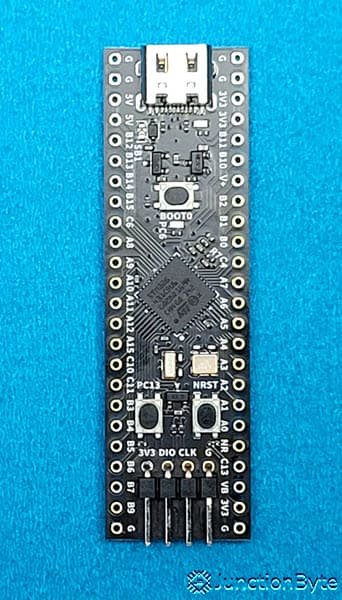
While I will be using the WeAct Studios STM32G431 Core Board (with STM32G431CBU6 MCU) in this guide, you can use this process to interface the 16×2 LCD Module with any STM32 Microcontroller.
Another important thing is the PCF8574 I2C LCD Module. Instead of directly connecting the LCD to the STM32G4 Microcontroller, which would require at least 7 GPIO Pins (4 for Data and 3 for Control) of the MCU, the PCF8574 I2C LCD Module limits the GPIO Pins to only 2 (I2C Pins – SDA and SCL).
With that information aside, let us dive straight into the STM32 I2C LCD Interface tutorial. In this tutorial, we will learn how to display text (ASCII Characters and some special/custom symbols) on an I2C LCD module using the STM32G431CBU6 microcontroller. The PCF8574 I2C backpack simplifies connections by reducing wiring complexity. We will use the STM32 HAL library and STM32CubeIDE for software development.
A Brief Note on 16×2 LCD
I have already talked a great deal about the 16×2 LCD Module in another tutorial (Interfacing 16×2 LCD with 8051 Microcontroller). This includes the pin diagram and pin functions of the 16×2 LCD, the Hitachi HD44780 LCD Controller, operating modes (4-bit and 8-bit), Commands, and many more. You can refer to that guide for in-depth information on all the important aspects of a typical 16×2 LCD.
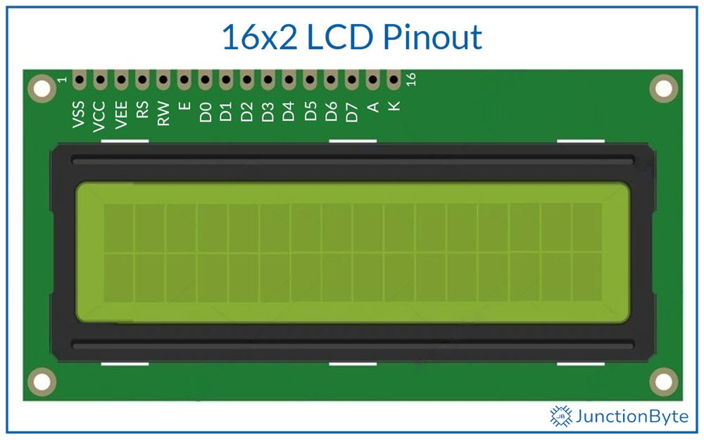
That said, here’s a quick recap. A 16×2 LCD, as the name suggests, shows two lines of 16 characters each. Each character is made up of a fixed grid of 5×8 pixels. These displays often have a blue or green backlight.
The Hitachi HD44780 is the primary driver for 16×2 character LCDs (even the 20×4 variant). This controller manages character generation, cursor control, and communication between the display and a microcontroller. It supports both 4-bit and 8-bit data modes.
Pin Configuration of a 16×2 LCD
The following list specifies a standard 16-pin interface for the 16×2 LCD Modules:
- VSS (GND): Connects to ground.
- VDD (or VCC): Supplies 5V power to the controller.
- V0 (or VEE): Controls contrast via a potentiometer.
- RS (Register Select): Switches between Command (LOW) and Data (HIGH) modes.
- R/W (Read/Write): Sets read from ROM (HIGH) or write to ROM (LOW) operations.
- E (Enable): Latches data on the falling edge.
- D0 – D7: Data lines for 8-bit mode (D4 – D7 for 4-bit mode).
- A (Anode): Backlight positive terminal.
- K (Cathode): Backlight negative terminal.
The RS pin determines whether the microcontroller sends commands (like clear screen) or data (like text characters). The E pin acts as a clock signal. It finalizes data transfer when it transitions HIGH to LOW.
A Brief Note PCF8574 I2C Module for LCD
While the STM32G4 MCUs have a decent number of GPIO Pins, it is still not practical to allocate a large number of GPIO Pins to a single I/O Device (in this case the 16×2 LCD). This is where special ICs such as the PCF8574 come in handy.
It is a IO Expander IC that communicates over I2C (I2C) with a Microcontroller and provides up to 8 additional GPIO Pins.
The PCF8574 I2C LCD Module is a special implementation of the PCF8574 IC that is specifically designed to connect to a 16×2 LCD Module. It has all the components (pull-up resistors for the I2C Data and Clock Lines, Potentiometer for LCD Contrast adjustment, Jumpers to set the I2C Address, and many more).
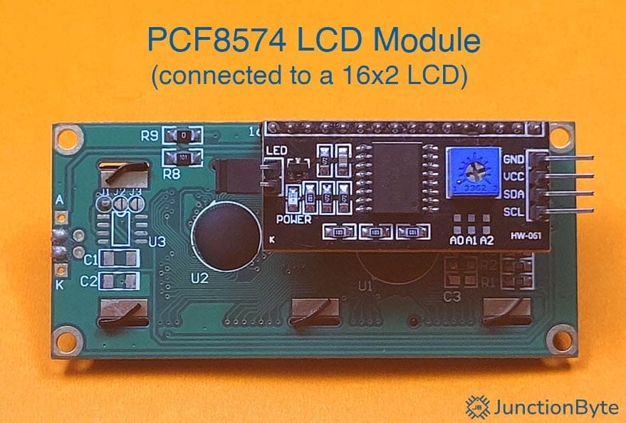
All you have to do is plug the PCF8574 I2C LCD Module at the back of a 16×2 LCD and display data using only two wires (SCL and SDA, apart from the Power Supply).
I’ll link some other guides on the PCF8574 IC that I made. You can refer to those guides for any additional information.
A Brief Note STM32G4
Coming to the main component of this project, I will be working with the STM32G4 MCU (specifically, the STM32G431CBU6 MCU). The STM32G4 Series of MCUs are relatively new in the STM32 line-up. They are much more powerful and faster than the widely popular STM32 Blue Pill.
I got a low-cost development board for the STM32G4 in the form of WeAct Studios STM32G431 Core Board. It is similar in formfactor to the STM32 Blue Pill, comes with a good deal of GPIO Pins, and uses USB-C for power and communication.
If you followed my previous exploration of the STM32G4, I made some “Getting Started with STM32G4” style guide. Here’s the links to those guides:
- Introduction to STM32G4
- Getting Started with STM32CubeIDE and STM32G4
- How to Program STM32G4 in PlatformIO?
Of these, the first two are very important as I discussed all the essentials that one might need to work with an STM32G4 MCU from scratch. This includes the pin diagram of the Development Board, how to configure Arduino IDE to work with STM32G4 MCUs, setting up STM32CubeIDE (creating the project, clock configuration, uploading the code using ST-Link or USB DFU). I highly recommend you to check those guides before proceeding further.
Components Needed to Interface PCF8574 I2C LCD with STM32G4
Hardware Requirements
- STM32G4 Development Board
- 16×2 LCD Module
- PCF8574 I2C LCD Adapter Board
- Breadboard
- Jumper Wires
- ST-Link Programmer (optional)
Software Requirements
- STM32CubeIDE (the latest version) with STM32G4 software pack
- ST-Link USB Drivers
- STM32CubeProgrammer (to upload firmware over USB)
Hardware Connections
| PCF8574 I2C LCD Module Pin | STM32G431CBU6 Pin |
| SDA | PB7 (I2C1_SDA) |
| SCL | PA15 (I2C1_SCL) |
| VCC | 5V |
| GND | GND |
We don’t need to add any pull-up resistors for the SDA and SCL lines as the PCF8574 I2C LCD Module takes care of that. I’ll explain the choice of pins for STM32G4’s I2C SDA and SCL in the next section.
STM32CubeIDE Project Configuration
Refer to my “Getting Started with STM32CubeIDE and STM32G4” guide for detailed project creation steps. I will go over these steps briefly.
Create a New Project
Open STM32CubeIDE and select “Start New STM32 Project” from the welcome dashboard. Alternatively, you can also create a new project by selecting File -> New -> STM32 Project.
The MCU selector (Target Selection) window pops open. In the “Commercial Part Number” search field, type “STM32G431CB” to filter devices and select “STM32G431CBU6” from the results on the right.
Click “Next,” then enter a suitable project name like “PCF8574_LCD_Interface” and choose a workspace directory. Leave the rest of the options at their default values (assuming you have the latest firmware package for STM32G4 HAL Drivers).
Setup Peripherals
In the “Device Configuration” view, navigate to the “Pinout & Configuration” tab. Expand “System Core” in the left panel and click on the “RCC” option. As my development board has a crystal oscillator for the main clock, I will set the “High Speed Clock (HSE)” to “Crystal/Ceramic Resonator” option. Later, I will show how to set the actual clock speed.
Next, within the “System Core,” click on “SYS” and set the “Debug” to “Serial Wire” option. Also make sure that the “Timebase Source” is “SysTick.”
Now, expand “Connectivity” in the left panel and expand the “I2C1” option. Enable “I2C1” by selecting “I2C” mode from the list.
STM32CubeIDE automatically assigns PA15 as I2C1_SCL and PB7 as I2C1_SDA. If you remember the Pinout of the STM32G4 Board, both these pins are 5V tolerant and are not assigned to any other functions.
Further, in the “Configuration” section, confirm that the “I2C Speed Mode” is set to “Standard Mode” and the “I2C Speed Frequency” is “100KHz.” You can leave the remaining parameters at their default values.
Clock Configuration
Click on the “Clock Configuration” tab to configure system clock settings. First, select HSE (external crystal) as the primary clock source (PLL Source Mux). If you want maximum MCU performance, we have to make sure that the System Clock (SYSCLK) runs at 170 MHz. For this, set the “HCLK” value as 170 (MHz) and hit enter. The IDE will automatically adjust different parameters and set the SYSCLK as 170 MHz.
If you scroll down, you can see the clock source for the I2C1 hardware block. Select either PCLK1 or SYSCLK as the clock source. The APB1 peripheral clock (PCLK1) must be at least four times faster than the I2C speed for proper operation.
Generate Project Code
After completing all configurations, save the Device Configuration options by pressing “Ctrl+s” and the IDE will ask whether to generate code or not. Click on “Yes.” The IDE will now ask whether to switch to C/C++ perspective and once again, click on “Yes.”
Alternatively, you can select Project -> Generate Code to generate the code.
PCF8574 I2C LCD Driver Code Implementation
Start by adding two new files to your STM32CubeIDE project. In the “Project Explorer”, right-click the “Drivers” folder and add a folder (New -> Folder). Let us call this “User_Driver”. Right-click this new folder (User_Driver) and add two more folders (name them “Inc” and “Src”).
It is time to add the driver files. Right-click the “Inc” folder and add a new header file (New -> Header File) and give it a name “PCF8574_I2C_LCD.h” (the extension .h is important).
Repeat the process in the Src folder to create the “PCF8574_I2C_LCD.c” file (but this time, create a Source File i.e., New -> Source File). These files will contain all LCD-specific functions and definitions.
PCF8574 I2C LCD Driver Header Code
Open the “PCF8574_I2C_LCD.h” and delete any auto-generated data. Copy and paste the following code and save the file. I have added comments for all the sections for easy understanding.
/**
  ******************************************************************************
  * @file    PCF8574_I2C_LCD.h
  * @brief   Header file for PCF8574-based I2C LCD driver.
  ******************************************************************************
  */

/* Define to prevent recursive inclusion -------------------------------------*/
#ifndef __PCF8574_I2C_LCD_H
#define __PCF8574_I2C_LCD_H

#ifdef __cplusplus
 extern "C" {
#endif

/* Includes ------------------------------------------------------------------*/
#include "stm32g4xx_hal.h"

/* Exported defines ----------------------------------------------------------*/

/* LCD Commands */
#define LCD_CLEARDISPLAY        0x01  /*!< Clear display command */
#define LCD_RETURNHOME          0x02  /*!< Return home command */
#define LCD_ENTRYMODESET        0x04  /*!< Set entry mode */
#define LCD_DISPLAYCONTROL      0x08  /*!< Display control */
#define LCD_CURSORSHIFT         0x10  /*!< Cursor shift */
#define LCD_FUNCTIONSET         0x20  /*!< Function set */
#define LCD_SETCGRAMADDR        0x40  /*!< Set CGRAM address */
#define LCD_SETDDRAMADDR        0x80  /*!< Set DDRAM address */

/* Flags for display entry mode */
#define LCD_ENTRYRIGHT          0x00
#define LCD_ENTRYLEFT           0x02
#define LCD_ENTRYSHIFTINCREMENT 0x01
#define LCD_ENTRYSHIFTDECREMENT 0x00

/* Flags for display on/off control */
#define LCD_DISPLAYON           0x04
#define LCD_DISPLAYOFF          0x00
#define LCD_CURSORON            0x02
#define LCD_CURSOROFF           0x00
#define LCD_BLINKON             0x01
#define LCD_BLINKOFF            0x00

/* Flags for function set */
#define LCD_8BITMODE            0x10
#define LCD_4BITMODE            0x00
#define LCD_2LINE               0x08
#define LCD_1LINE               0x00
#define LCD_5x10DOTS            0x04
#define LCD_5x8DOTS             0x00

/* PCF8574 pin mapping */
#define PCF8574_PIN_RS  (1 << 0)
#define PCF8574_PIN_RW  (1 << 1)
#define PCF8574_PIN_EN  (1 << 2)
#define PCF8574_PIN_BL  (1 << 3)
#define PCF8574_DATA_MASK 0xF0

/* Exported types ------------------------------------------------------------*/

/**
  * @brief  PCF8574 LCD Handle Structure definition
  */
typedef struct {
    I2C_HandleTypeDef *hi2c;      /*!< Pointer to HAL I2C handle */
    uint8_t address;              /*!< I2C address of the PCF8574 */
    uint8_t display_control;      /*!< Display control flags */
    uint8_t display_function;     /*!< Function set flags */
    uint8_t display_mode;         /*!< Entry mode flags */
    uint8_t backlight;            /*!< Backlight control flag */
} PCF8574_LCD_HandleTypeDef;

/* Exported functions --------------------------------------------------------*/

/**
  * @brief  Initializes the LCD.
  * @param  lcd: Pointer to a PCF8574_LCD_HandleTypeDef structure.
  * @retval None
  */
void LCD_Init(PCF8574_LCD_HandleTypeDef *lcd);

/**
  * @brief  Clears the LCD display.
  * @param  lcd: Pointer to a PCF8574_LCD_HandleTypeDef structure.
  * @retval None
  */
void LCD_Clear(PCF8574_LCD_HandleTypeDef *lcd);

/**
  * @brief  Returns the cursor to home position.
  * @param  lcd: Pointer to a PCF8574_LCD_HandleTypeDef structure.
  * @retval None
  */
void LCD_Home(PCF8574_LCD_HandleTypeDef *lcd);

/**
  * @brief  Sets the cursor position.
  * @param  lcd: Pointer to a PCF8574_LCD_HandleTypeDef structure.
  * @param  col: Column position.
  * @param  row: Row position.
  * @retval None
  */
void LCD_SetCursor(PCF8574_LCD_HandleTypeDef *lcd, uint8_t col, uint8_t row);

/**
  * @brief  Prints a string to the LCD.
  * @param  lcd: Pointer to a PCF8574_LCD_HandleTypeDef structure.
  * @param  str: Null-terminated string to print.
  * @retval None
  */
void LCD_Print(PCF8574_LCD_HandleTypeDef *lcd, const char *str);

/**
  * @brief  Sends a command to the LCD.
  * @param  lcd: Pointer to a PCF8574_LCD_HandleTypeDef structure.
  * @param  cmd: Command byte.
  * @retval None
  */
void LCD_Command(PCF8574_LCD_HandleTypeDef *lcd, uint8_t cmd);

/**
  * @brief  Writes a single character to the LCD.
  * @param  lcd: Pointer to a PCF8574_LCD_HandleTypeDef structure.
  * @param  c: Character to display.
  * @retval None
  */
void LCD_WriteChar(PCF8574_LCD_HandleTypeDef *lcd, char c);

/**
  * @brief  Controls the LCD backlight.
  * @param  lcd: Pointer to a PCF8574_LCD_HandleTypeDef structure.
  * @param  state: 1 to turn on, 0 to turn off.
  * @retval None
  */
void LCD_Backlight(PCF8574_LCD_HandleTypeDef *lcd, uint8_t state);

/**
  * @brief  Creates a custom character.
  * @param  lcd: Pointer to a PCF8574_LCD_HandleTypeDef structure.
  * @param  location: Character memory location (0-7).
  * @param  charmap: Array of 8 bytes defining the custom character.
  * @retval None
  */
void LCD_CreateChar(PCF8574_LCD_HandleTypeDef *lcd, uint8_t location, uint8_t charmap[]);

#ifdef __cplusplus
}
#endif

#endif /* __PCF8574_I2C_LCD_H */
PCF8574 I2C LCD Driver Source Code
Perform a similar action, but this time for the source code (“PCF8574_I2C_LCD.c”). Again, refer to the comments and learn how the code works.
/**
  ******************************************************************************
  * @file    PCF8574_I2C_LCD.c
  * @brief   Source file for PCF8574-based I2C LCD driver.
  ******************************************************************************
  */

/* Includes ------------------------------------------------------------------*/
#include "PCF8574_I2C_LCD.h"
#include <string.h>
#include <stdint.h>
#include <stdio.h>

/* Private function prototypes -----------------------------------------------*/
static void LCD_WriteNibble(PCF8574_LCD_HandleTypeDef *lcd, uint8_t nibble, uint8_t rs);
static void LCD_Write(PCF8574_LCD_HandleTypeDef *lcd, uint8_t data, uint8_t rs);

/* Exported functions --------------------------------------------------------*/

/**
  * @brief  Initializes the LCD module.
  * @param  lcd: Pointer to a PCF8574_LCD_HandleTypeDef structure.
  * @retval None
  */
void LCD_Init(PCF8574_LCD_HandleTypeDef *lcd) {
    /* Wait for LCD to power up */
    HAL_Delay(50);
    lcd->backlight = PCF8574_PIN_BL;

    /* Initialize LCD in 4-bit mode */
    LCD_WriteNibble(lcd, 0x30, 0);
    HAL_Delay(5);
    LCD_WriteNibble(lcd, 0x30, 0);
    HAL_Delay(5);
    LCD_WriteNibble(lcd, 0x30, 0);
    HAL_Delay(5);
    LCD_WriteNibble(lcd, 0x20, 0);

    /* Function set: 4-bit mode, 2 lines, 5x8 dots */
    lcd->display_function = LCD_4BITMODE | LCD_2LINE | LCD_5x8DOTS;
    LCD_Command(lcd, LCD_FUNCTIONSET | lcd->display_function);

    /* Display control: display on, cursor off, blink off */
    lcd->display_control = LCD_DISPLAYON | LCD_CURSOROFF | LCD_BLINKOFF;
    LCD_Command(lcd, LCD_DISPLAYCONTROL | lcd->display_control);

    /* Entry mode set: left to right, no display shift */
    lcd->display_mode = LCD_ENTRYLEFT | LCD_ENTRYSHIFTDECREMENT;
    LCD_Command(lcd, LCD_ENTRYMODESET | lcd->display_mode);

    /* Clear display */
    LCD_Clear(lcd);
}

/**
  * @brief  Clears the LCD display.
  * @param  lcd: Pointer to a PCF8574_LCD_HandleTypeDef structure.
  * @retval None
  */
void LCD_Clear(PCF8574_LCD_HandleTypeDef *lcd) {
    LCD_Command(lcd, LCD_CLEARDISPLAY);
    HAL_Delay(2); /* Clear command requires >1.52ms delay */
}

/**
  * @brief  Sets the cursor to home position.
  * @param  lcd: Pointer to a PCF8574_LCD_HandleTypeDef structure.
  * @retval None
  */
void LCD_Home(PCF8574_LCD_HandleTypeDef *lcd) {
    LCD_Command(lcd, LCD_RETURNHOME);
    HAL_Delay(2); /* Return home command delay */
}

/**
  * @brief  Sets the cursor position on the LCD.
  * @param  lcd: Pointer to a PCF8574_LCD_HandleTypeDef structure.
  * @param  col: Column position.
  * @param  row: Row position.
  * @retval None
  */
void LCD_SetCursor(PCF8574_LCD_HandleTypeDef *lcd, uint8_t col, uint8_t row) {
    uint8_t row_offsets[] = {0x00, 0x40, 0x14, 0x54};
    LCD_Command(lcd, LCD_SETDDRAMADDR | (col + row_offsets[row]));
}

/**
  * @brief  Prints a null-terminated string to the LCD.
  * @param  lcd: Pointer to a PCF8574_LCD_HandleTypeDef structure.
  * @param  str: Pointer to the string to display.
  * @retval None
  */
void LCD_Print(PCF8574_LCD_HandleTypeDef *lcd, const char *str) {
    while (*str) {
        LCD_WriteChar(lcd, *str++);
    }
}

/**
  * @brief  Sends a command byte to the LCD.
  * @param  lcd: Pointer to a PCF8574_LCD_HandleTypeDef structure.
  * @param  cmd: Command byte.
  * @retval None
  */
void LCD_Command(PCF8574_LCD_HandleTypeDef *lcd, uint8_t cmd) {
    LCD_Write(lcd, cmd, 0);
}

/**
  * @brief  Writes a single character to the LCD.
  * @param  lcd: Pointer to a PCF8574_LCD_HandleTypeDef structure.
  * @param  c: Character to be written.
  * @retval None
  */
void LCD_WriteChar(PCF8574_LCD_HandleTypeDef *lcd, char c) {
    LCD_Write(lcd, c, PCF8574_PIN_RS);
}

/**
  * @brief  Controls the LCD backlight.
  * @param  lcd: Pointer to a PCF8574_LCD_HandleTypeDef structure.
  * @param  state: 1 to enable, 0 to disable the backlight.
  * @retval None
  */
void LCD_Backlight(PCF8574_LCD_HandleTypeDef *lcd, uint8_t state) {
    lcd->backlight = state ? PCF8574_PIN_BL : 0;
    uint8_t data = lcd->backlight;
    HAL_I2C_Master_Transmit(lcd->hi2c, lcd->address << 1, &data, 1, HAL_MAX_DELAY);
}

/**
  * @brief  Creates a custom character.
  * @param  lcd: Pointer to a PCF8574_LCD_HandleTypeDef structure.
  * @param  location: CGRAM location (0 to 7) where the custom character will be stored.
  * @param  charmap: Array of 8 bytes that define the character.
  * @retval None
  */
void LCD_CreateChar(PCF8574_LCD_HandleTypeDef *lcd, uint8_t location, uint8_t charmap[]) {
    location &= 0x7; /* We only have 8 locations: 0-7 */
    LCD_Command(lcd, LCD_SETCGRAMADDR | (location << 3));
    for (int i = 0; i < 8; i++) {
        LCD_WriteChar(lcd, charmap[i]);
    }
}

/* Private functions ---------------------------------------------------------*/

/**
  * @brief  Writes data in 4-bit mode to the LCD.
  * @param  lcd: Pointer to a PCF8574_LCD_HandleTypeDef structure.
  * @param  data: Data byte to be sent.
  * @param  rs: Register select flag (0 = command, PCF8574_PIN_RS = data).
  * @retval None
  */
static void LCD_Write(PCF8574_LCD_HandleTypeDef *lcd, uint8_t data, uint8_t rs) {
    LCD_WriteNibble(lcd, data & 0xF0, rs);
    LCD_WriteNibble(lcd, (data << 4) & 0xF0, rs);
}

/**
  * @brief  Sends a single nibble to the LCD with proper timing.
  * @param  lcd: Pointer to a PCF8574_LCD_HandleTypeDef structure.
  * @param  nibble: Upper 4 bits to be sent.
  * @param  rs: Register select flag.
  * @retval None
  */
static void LCD_WriteNibble(PCF8574_LCD_HandleTypeDef *lcd, uint8_t nibble, uint8_t rs) {
    uint8_t data = nibble | rs | lcd->backlight | PCF8574_PIN_EN;
    HAL_I2C_Master_Transmit(lcd->hi2c, lcd->address << 1, &data, 1, HAL_MAX_DELAY);
    HAL_Delay(1);
    data &= ~PCF8574_PIN_EN;
    HAL_I2C_Master_Transmit(lcd->hi2c, lcd->address << 1, &data, 1, HAL_MAX_DELAY);
    HAL_Delay(1);
}
Main Application Code to Interface PCF8574 I2C LCD with STM32G4
The STM32CubeIDE will automatically generate a default “main.c” file (Core -> Src -> main.c). Open this file and replace its contents with the following sample application code.
/* USER CODE BEGIN Header */
/**
******************************************************************************
* @file : main.c
* @brief : Main program body
******************************************************************************
* @attention
*
* Copyright (c) 2025 STMicroelectronics.
* All rights reserved.
*
* This software is licensed under terms that can be found in the LICENSE file
* in the root directory of this software component.
* If no LICENSE file comes with this software, it is provided AS-IS.
*
******************************************************************************
*/
/* USER CODE END Header */
/* Includes ------------------------------------------------------------------*/
#include "main.h"
/* Private includes ----------------------------------------------------------*/
/* USER CODE BEGIN Includes */
#include "PCF8574_I2C_LCD.h"
/* USER CODE END Includes */
/* Private typedef -----------------------------------------------------------*/
/* USER CODE BEGIN PTD */
/* USER CODE END PTD */
/* Private define ------------------------------------------------------------*/
/* USER CODE BEGIN PD */
/* USER CODE END PD */
/* Private macro -------------------------------------------------------------*/
/* USER CODE BEGIN PM */
/* USER CODE END PM */
/* Private variables ---------------------------------------------------------*/
I2C_HandleTypeDef hi2c1;
/* USER CODE BEGIN PV */
/* Create LCD handle */
PCF8574_LCD_HandleTypeDef lcd;
uint8_t smiley[8] = {
0x00,
0x0A,
0x00,
0x00,
0x11,
0x0E,
0x00,
0x00
};
/* USER CODE END PV */
/* Private function prototypes -----------------------------------------------*/
void SystemClock_Config(void);
static void MX_GPIO_Init(void);
static void MX_I2C1_Init(void);
/* USER CODE BEGIN PFP */
/* USER CODE END PFP */
/* Private user code ---------------------------------------------------------*/
/* USER CODE BEGIN 0 */
/* USER CODE END 0 */
/**
* @brief The application entry point.
* @retval int
*/
int main(void)
{
/* USER CODE BEGIN 1 */
/* USER CODE END 1 */
/* MCU Configuration--------------------------------------------------------*/
/* Reset of all peripherals, Initializes the Flash interface and the Systick. */
HAL_Init();
/* USER CODE BEGIN Init */
/* USER CODE END Init */
/* Configure the system clock */
SystemClock_Config();
/* USER CODE BEGIN SysInit */
/* USER CODE END SysInit */
/* Initialize all configured peripherals */
MX_GPIO_Init();
MX_I2C1_Init();
/* USER CODE BEGIN 2 */
/* Set up LCD handle */
lcd.hi2c = &hi2c1;
lcd.address = 0x3F; /* Common I2C address. Change if needed.*/
/* Initialize LCD */
LCD_Init(&lcd);
LCD_Backlight(&lcd, 1); // Turn backlight on
LCD_CreateChar(&lcd, 0, smiley); /* Create custom char at location 0 */
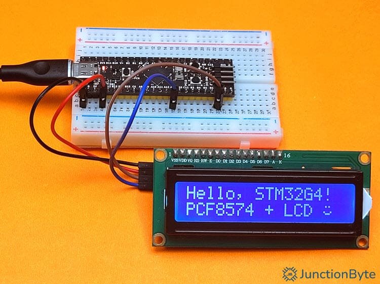
/* Display a message */
LCD_SetCursor(&lcd, 0, 0);
LCD_Print(&lcd, "Hello, STM32G4!");
LCD_SetCursor(&lcd, 0, 1);
LCD_Print(&lcd, "PCF8574 + LCD");
LCD_SetCursor(&lcd, 14, 1);
LCD_WriteChar(&lcd, 0); /* Display the custom char */
/* USER CODE END 2 */
/* Infinite loop */
/* USER CODE BEGIN WHILE */
while (1)
{
/* USER CODE END WHILE */
/* USER CODE BEGIN 3 */
}
/* USER CODE END 3 */
}
/**
* @brief System Clock Configuration
* @retval None
*/
void SystemClock_Config(void)
{
RCC_OscInitTypeDef RCC_OscInitStruct = {0};
RCC_ClkInitTypeDef RCC_ClkInitStruct = {0};
/** Configure the main internal regulator output voltage
*/
HAL_PWREx_ControlVoltageScaling(PWR_REGULATOR_VOLTAGE_SCALE1_BOOST);
/** Initializes the RCC Oscillators according to the specified parameters
* in the RCC_OscInitTypeDef structure.
*/
RCC_OscInitStruct.OscillatorType = RCC_OSCILLATORTYPE_HSE;
RCC_OscInitStruct.HSEState = RCC_HSE_ON;
RCC_OscInitStruct.PLL.PLLState = RCC_PLL_ON;
RCC_OscInitStruct.PLL.PLLSource = RCC_PLLSOURCE_HSE;
RCC_OscInitStruct.PLL.PLLM = RCC_PLLM_DIV2;
RCC_OscInitStruct.PLL.PLLN = 85;
RCC_OscInitStruct.PLL.PLLP = RCC_PLLP_DIV2;
RCC_OscInitStruct.PLL.PLLQ = RCC_PLLQ_DIV2;
RCC_OscInitStruct.PLL.PLLR = RCC_PLLR_DIV2;
if (HAL_RCC_OscConfig(&RCC_OscInitStruct) != HAL_OK)
{
Error_Handler();
}
/** Initializes the CPU, AHB and APB buses clocks
*/
RCC_ClkInitStruct.ClockType = RCC_CLOCKTYPE_HCLK|RCC_CLOCKTYPE_SYSCLK
|RCC_CLOCKTYPE_PCLK1|RCC_CLOCKTYPE_PCLK2;
RCC_ClkInitStruct.SYSCLKSource = RCC_SYSCLKSOURCE_PLLCLK;
RCC_ClkInitStruct.AHBCLKDivider = RCC_SYSCLK_DIV1;
RCC_ClkInitStruct.APB1CLKDivider = RCC_HCLK_DIV1;
RCC_ClkInitStruct.APB2CLKDivider = RCC_HCLK_DIV1;
if (HAL_RCC_ClockConfig(&RCC_ClkInitStruct, FLASH_LATENCY_4) != HAL_OK)
{
Error_Handler();
}
}
/**
* @brief I2C1 Initialization Function
* @param None
* @retval None
*/
static void MX_I2C1_Init(void)
{
/* USER CODE BEGIN I2C1_Init 0 */
/* USER CODE END I2C1_Init 0 */
/* USER CODE BEGIN I2C1_Init 1 */
/* USER CODE END I2C1_Init 1 */
hi2c1.Instance = I2C1;
hi2c1.Init.Timing = 0x40B285C2;
hi2c1.Init.OwnAddress1 = 0;
hi2c1.Init.AddressingMode = I2C_ADDRESSINGMODE_7BIT;
hi2c1.Init.DualAddressMode = I2C_DUALADDRESS_DISABLE;
hi2c1.Init.OwnAddress2 = 0;
hi2c1.Init.OwnAddress2Masks = I2C_OA2_NOMASK;
hi2c1.Init.GeneralCallMode = I2C_GENERALCALL_DISABLE;
hi2c1.Init.NoStretchMode = I2C_NOSTRETCH_DISABLE;
if (HAL_I2C_Init(&hi2c1) != HAL_OK)
{
Error_Handler();
}
/** Configure Analogue filter
*/
if (HAL_I2CEx_ConfigAnalogFilter(&hi2c1, I2C_ANALOGFILTER_ENABLE) != HAL_OK)
{
Error_Handler();
}
/** Configure Digital filter
*/
if (HAL_I2CEx_ConfigDigitalFilter(&hi2c1, 0) != HAL_OK)
{
Error_Handler();
}
/* USER CODE BEGIN I2C1_Init 2 */
/* USER CODE END I2C1_Init 2 */
}
/**
* @brief GPIO Initialization Function
* @param None
* @retval None
*/
static void MX_GPIO_Init(void)
{
GPIO_InitTypeDef GPIO_InitStruct = {0};
/* USER CODE BEGIN MX_GPIO_Init_1 */
/* USER CODE END MX_GPIO_Init_1 */
/* GPIO Ports Clock Enable */
__HAL_RCC_GPIOC_CLK_ENABLE();
__HAL_RCC_GPIOF_CLK_ENABLE();
__HAL_RCC_GPIOA_CLK_ENABLE();
__HAL_RCC_GPIOB_CLK_ENABLE();
/*Configure GPIO pin Output Level */
HAL_GPIO_WritePin(LED_GPIO_Port, LED_Pin, GPIO_PIN_RESET);
/*Configure GPIO pin : Button_Pin */
GPIO_InitStruct.Pin = Button_Pin;
GPIO_InitStruct.Mode = GPIO_MODE_INPUT;
GPIO_InitStruct.Pull = GPIO_PULLDOWN;
HAL_GPIO_Init(Button_GPIO_Port, &GPIO_InitStruct);
/*Configure GPIO pin : LED_Pin */
GPIO_InitStruct.Pin = LED_Pin;
GPIO_InitStruct.Mode = GPIO_MODE_OUTPUT_PP;
GPIO_InitStruct.Pull = GPIO_NOPULL;
GPIO_InitStruct.Speed = GPIO_SPEED_FREQ_LOW;
HAL_GPIO_Init(LED_GPIO_Port, &GPIO_InitStruct);
/* USER CODE BEGIN MX_GPIO_Init_2 */
/* USER CODE END MX_GPIO_Init_2 */
}
/* USER CODE BEGIN 4 */
/* USER CODE END 4 */
/**
* @brief This function is executed in case of error occurrence.
* @retval None
*/
void Error_Handler(void)
{
/* USER CODE BEGIN Error_Handler_Debug */
/* User can add his own implementation to report the HAL error return state */
__disable_irq();
while (1)
{
}
/* USER CODE END Error_Handler_Debug */
}
#ifdef USE_FULL_ASSERT
/**
* @brief Reports the name of the source file and the source line number
* where the assert_param error has occurred.
* @param file: pointer to the source file name
* @param line: assert_param error line source number
* @retval None
*/
void assert_failed(uint8_t *file, uint32_t line)
{
/* USER CODE BEGIN 6 */
/* User can add his own implementation to report the file name and line number,
ex: printf("Wrong parameters value: file %s on line %d\r\n", file, line) */
/* USER CODE END 6 */
}
#endif /* USE_FULL_ASSERT */
Upload Firmware to ST32G4 MCU
Build the Project
The first step is to build the project. Inside STM32CubeIDE, press the hammer icon located at the top toolbar to start the build process. Sadly, the build process will fail and if you monitor the “Console” tab at the bottom, you will understand the reason for compilation errors during the build.
We have added the driver files to our project but did not inform the compiler to include these files during compilation. Let me explain how to resolve this issue.
Go to Project -> Properties. Expand the “C/C++ General” tab on the left and click on “Paths and Symbols” option. In the “Includes” tab, make sure that “GNU C” is the language selected and click on the “Add..” option on the right.
Now, click on “Workspace..” and navigate to the “Inc” folder that we created. The path should be something like this “Drivers/User_Driver/Inc” and make sure that it is marked as a workspace path.
After this, if you try to build the project once again, I am sure the action will be successful.
Flash the Firmware to the STM32G4 MCU
I have discussed in great detail how to upload the code to an STM32G4 development board in my STM32CubeIDE tutorial. If you have the ST-Link hardware, connect your STM32G4 board to the computer using a USB cable through the ST-Link programmer.
Select “Run > Run” from the top menu bar to flash the compiled binary directly to the MCU’s internal flash memory. You can also use the green “play” button to flash the MCU.
If everything goes well, you should be able to see the sample text on the 16×2 LCD.
Conclusion
In this project, we successfully interfaced a PCF8574-based I2C LCD module with the STM32G431CBU6 microcontroller (through the WeAct Studios STM32G431 Core Board). You can apply the same procedure to any STM32 MCU.
We used STM32CubeIDE to configure the I2C peripheral and manage the project structure.
While the STM32CubeIDE took care of all the “HAL” libraries, we created the driver for PCF8574 I2C LCD Module from scratch without relying on third-party libraries. The driver allows precise control of the LCD display through I2C commands.
If you faced any problems following this guide or understanding any part of the driver code, do let me know in the comments section. I will respond with a suitable solution.