The Nokia 5110 LCD module, originally designed for Nokia mobile phones (such as the Nokia 5110 and Nokia 3310), became popular in the hobbyist, DIY, and embedded community due to its simplicity, low cost, ease of interfacing, and clear readability under various lighting conditions. Its resolution of 84×48 pixels is good enough for displaying characters, basic graphics, and simple animations. In this tutorial, we will explore how to interface a Nokia 5110 LCD with an STM32G4 microcontroller.
I have been using the WeAct Studios STM32G431 Core Board (with STM32G431CBU6 MCU) for this series and will continue with the same. For software development, we will use STM32CubeIDE and the STM32 HAL framework. The primary goal of this tutorial is to build a driver for the Nokia 5110 LCD using STM32 HAL as a base.
A Brief Note on Nokia 5110 LCD
The Nokia 5110 LCD is a small, monochrome display that became widely known for its use in the Nokia 5110 mobile phone released in the late 1990s. Once mobile phones began using more advanced display technologies, the Nokia 5110 LCD was phased out in favor of better, color displays.
However, the simple interface and low cost of the Nokia 5110 LCD sparked new interest among DIY electronics enthusiasts and engineers. Arduino enthusiasts, in particular, adopted this display for a wide range of applications, from simple text-based output to more complex graphical interfaces. The availability of libraries made it easy for users to integrate the LCD with popular microcontroller platforms like Arduino, Raspberry Pi, and STM32.

The Nokia 5110 LCD has a resolution of 84 x 48 pixels. While the resolution is not high by modern standards, this pixel count is sufficient for many embedded system applications. With this resolution, we can easily display simple text, basic graphics, and icons.
The display has backlighting, which vastly improves visibility in low-light environments. Power consumption typically ranges from 1.5mA to 5mA for the display itself, while the backlight can draw up to 20mA.
Operating voltage ranges from 2.7V to 3.3V. Since we are working to interface Nokia 5110 LCD with STM32G4 MCU (which also operates at 3.3V), we don’t have to worry about voltage levels. However, if you are using a 5V microcontroller (such as an Arduino), then you need to use level shifters.
A Brief Note on PCD8544 LCD Controller/Driver
The Philips PCD8544 LCD Controller/Driver is a key component in managing the operation of the Nokia 5110 display, which includes controlling every pixel on the 84×48 monochrome display. This controller communicates via SPI (Serial Peripheral Interface) with microcontrollers and operates at clock speeds up to 4 MHz.
It takes data from the microcontroller and converts it into commands that control how pixels are displayed on the screen. PCD8544 handles critical tasks like memory buffering, contrast adjustment, and power management.
The memory organization of the PCD8544 is simple and straightforward. It uses a frame buffer (RAM) to store pixel data. The memory is divided into 48 rows and 84 columns, with each pixel represented by one bit.
We can access each row individually, which makes it easy to control individual lines of pixels. The 48×84-bit RAM buffer is mapped directly to the pixel grid on the display. The controller refreshes this buffer at approximately 70 Hz to prevent any visible flicker during updates.
PCD8544 LCD Driver Memory Map
The PCD8544 has 504 Bytes of RAM Buffer (or GDDRAM – Graphic Display Data RAM). The memory is divided into 6 horizontal banks (Bank 0 to 5) and each bank is further divided into 84 columns or segments. Each of these columns can store a Byte of data (8 bits for 8 vertical pixels) where each bit corresponds to one pixel.
So, total memory size = 6 Banks × 84 Columns (Segments) × 8 Bits = 4,032 Bits (504 Bytes).
Each byte controls a vertical slice of 8 pixels for a particular column. For example, if you write 0xFF to a memory location, it turns ON all 8 pixels vertically at that column and row-bank. Writing 0x00 would turn them all OFF.
How the Memory Addresses Work?
We can address the memory map using two key parameters:
- X-address: Selects the column (0–83).
- Y-address: Selects the bank (0–5).
Before writing data to the display, we must first set the X and Y addresses. After setting these addresses, you send the data byte, which updates the 8 vertical pixels in that column and bank.
After you write a byte, the X-address auto-increments by 1.
Pinout Diagram of the Nokia 5110 LCD
The Nokia 5110 LCD has a total of 8 pins. Here’s a table that outlines the pins of the Nokia 5110 LCD (in order), along with their functions.
| Pin | Symbol | Name | Function |
| 1 | RST | Reset | Resets the LCD to its default state. Typically pulled LOW briefly during initialization. |
| 2 | CE | Chip Enable | When LOW, the display is active; when HIGH, the display is disabled or in sleep mode. |
| 3 | DC | Data/Command Selector | When LOW, the controller interprets the incoming data as commands; when HIGH, it interprets the data as display data. |
| 4 | DIN | Data In | Serial data input pin. Carries the data or commands to be sent to the LCD from MCU. |
| 5 | CLK | Clock | Serial clock input. It provides timing for the data transfer. Each clock pulse shifts one bit of data from DIN. |
| 6 | VCC | Power Supply | Connects to the positive voltage supply (typically 3.3V or 5V) to power the display. |
| 7 | BL | Backlight Control | Controls the backlight of the display. Requires an external resistor to limit current to the LEDs. May be tied to a GPIO pin for control. |
| 8 | GND | Ground | Connects to the ground of the power source. |
Nokia 5110 LCD Communication Protocol
The Nokia 5110 LCD (or rather, the PCD8544 controller) uses a synchronous serial interface to communicate with the microcontroller. It uses a form of serial communication that resembles the Serial Peripheral Interface (SPI) protocol but with some key differences.
For data transfer, the Nokia 5110 LCD uses three lines: a clock line (CLK), a data input line (DIN), and a chip enable (CE) pin. The PCD8544 expects data to be sent bit by bit over the DIN line, synchronized with the clock pulses from the CLK line.
One key difference between the PCD8544 interface and traditional SPI is the lack of a separate MISO (Master In Slave Out) line. This display does not send data back to the microcontroller during operation.
How Does PCD8544 Distinguish between Command and Data?
The D/C (Data/Command) pin plays a key role in distinguishing between instructions (commands) and display data. When the D/C pin is LOW, the PCD8544 controller enters command mode. In this mode, the data being sent over the DIN line is treated as a command that controls the behavior of the display. Commands can include instructions for initializing the display, adjusting contrast, or clearing the screen.
When the D/C pin is set HIGH, the PCD8544 enters data mode. In this mode, the data sent over the DIN line is treated as pixel data, which is displayed on the screen.
Hardware Setup to Interface Nokia 5110 LCD with STM32G4
Components Needed
- STM32G4 Development Board
- Nokia 5110 LCD
- Breadboard
- Jumper Wires
Pin Connections between Nokia 5110 LCD and STM32G4
Let us start with the power. My Nokia 5110 LCD accepts VCC between 3V and 5V. However, this might not be the case with all the displays. To be on the safe side, I connected the VCC pin to the 3.3V supply on the STM32 Board. Similarly, GND connects to the ground pin on the board.
There are two SPI Pins (DIN and CLK) that connect to the corresponding SPI Pins of the STM32G4. I will be using SPI1 of the STM32G431CBU6 MCU. So, DIN connects to PA7 and CLK to PA5.
Next, we have three control pins: DC, CE, and RST. As we will use software control for these pins, we can connect them to any free GPIO Pins (that are configured as GPIO_Output). In my case, I connected DC to PA1, CE to PA2, and RST to PA3.
We are left with the Backlight (BL) Pin. If we want the backlight to be on continuously, then we can connect the BL pin to 3.3V through a series current-limiting resistor, typically 100 Ω.
However, if we connect this to a GPIO Pin, we can control the backlight through software (simple ON/OFF or PWM). So, I connected the BL pin to PA0.
| Nokia 5110 LCD | STM32G4 (STM32G431CBU6) |
| RST | PA3 |
| CE | PA2 |
| DC | PA1 |
| DIN | PA7 |
| CLK | PA5 |
| VCC | 3.3V |
| BL | PA0 |
| GND | GND |
STM32CubeIDE Project Setup
If you are familiar with setting up and configuring the STM32CubeIDE environment, you can skip this section. However, I will discuss some important optimization and key configurations for the SPI peripheral of the STM32G4 MCU. So, if you are relatively new to STM32CubeIDE, then continue reading this part of the guide.
Create a New Project
Open STM32CubeIDE and start a new STM32 project (File -> New -> STM32 Project from the top menu). A ‘Target Selector’ window will appear. In the search bar (next to ‘Commercial Part Number’), type ‘STM32G431CBU6,’ select the correct MCU from the results on the right, and click Next.
Give the project a suitable name, such as ‘Nokia5110_LCD_Interface.’ You can leave the rest of the options at their default and click Finish to create the project structure.
The IDE will open the IOC (pin configuration) window. We can now set up the MCU peripherals through this interface.
Configure SPI
Before we configure the SPI Peripheral, let us quickly set some basic parameters. First, in the ‘Pinout & Configuration’ tab, expand the ‘System Core’ and click on ‘RCC.’ Make the ‘High Speed Clock (HSE)’ to ‘Crystal/Ceramic Resonator.’ Next, click on ‘SYS’ and set the ‘Debug’ to ‘Serial Wire.’
Coming to SPI, expand ‘Connectivity’ on the left, and click on ‘SPI.’ Since the Nokia 5110 LCD or the PCD8544 Controller doesn’t send any data back to the microcontroller, we can save a pin of the MCU by using only the ‘MOSI’ pin of the SPI.
For this, set the ‘Mode’ to ‘Transmit Only Master’ and you can see that only two Pins became active (PA5 as SPI1_SCK and PA7 as SPI1_MOSI). You can leave the ‘Hardware NSS Signal’ as ‘Disable’ as we will be using software to control the Chip Select or Chip Enable pin of the Nokia 5110 LCD.
In the ‘Configuration’ section below, set the data size to ‘8 Bits’ and the first bit should be MSB. For SPI Clock, the maximum clock speed that the PCD8544 Controller supports is 4MHz. Since we will be operating the STM32G4 MCU at 170MHz, we can use a prescaler of 32 to set the SPI Clock at 5.3125MHz. This is slightly higher than 4MHz but would be fine.
Next, set the clock polarity (CPOL) to Low and clock phase (CPHA) to 1st Edge because the Nokia 5110 expects data to be sampled on the rising clock edge. Make sure that the ‘NSS Signal Type’ is set to ‘Software.’
Configure GPIOs
The previous section completes only the SPI Pin selection and configuration. However, if you look at the Pinout of Nokia 5110 LCD, we have three more pins to configure: RST, CE, and DS (four if we include the BL Pin as well).
You can see the GPIO Pins that I assigned to these four pins along with the labels in the following table. The modes of all these pins must be ‘GPIO_Output.’
| Nokia 5110 LCD Pin | STM32G4 Pin | Pin Label |
| BL | PA0 | NOKIA5110_BL |
| DC | PA1 | NOKIA5110_DC |
| CE | PA2 | NOKIA5110_CE |
| RST | PA3 | NOKIA5110_RST |
Clock Configuration
Select the ‘Clock Configuration’ and set the ‘PLL Source Mux’ to ‘HSE’ and ‘System Clock Mux’ to ‘PLLCLK.’
Now, set the value of ‘HCLK’ as 170 and hit enter. The IDE will automatically configure the rest of the parameters to set the 170 MHz CPU clock speed.
Generate Code
Just save the IOC file (by pressing Ctrl+s) and the IDE will automatically generate the starting code for you.
Nokia 5110 LCD Driver Code
I divided the Nokia 5110 LCD Driver into two files: header (.h) and source (.c). Before looking at the driver code, we need to modify the structure of the project by adding a couple of folders and files.
In the “Project Explorer”, right-click the “Drivers” folder and add a folder (New -> Folder). Let us call this ‘User_Driver.’ Right-click the ‘User_Driver’ folder and add two more folders (name them ‘Inc’ and ‘Src’).
Now, right-click the ‘Inc’ folder and add a new header file (New -> Header File) and give it the name ‘NOKIA5110-LCD.h (don’t forget the .h extension).
Similarly, add ‘NOKIA5110-LCD.c’ file in the Src folder (by creating a Source File i.e., New -> Source File).
Nokia 5110 LCD Driver Header Code
Open the newly created header file (NOKIA5110-LCD.h) and delete any auto-generated data. Copy and paste the following code (and save the file). The header file is simple as it contains pin definitions, function prototypes, and font data.
/**
  ******************************************************************************
  * @file    NOKIA5110_LCD.h
  * @brief   Driver header for Nokia 5110 LCD (PCD8544) using STM32 HAL.
  ******************************************************************************
  * @attention
  *
  * This header file provides function prototypes and definitions required for
  * interfacing the Nokia 5110 LCD module with an STM32 MCU via SPI using HAL.
  * It now includes functions for contrast and backlight PWM control and a basic
  * graphics API with a frame buffer to draw pixels, lines, shapes, and text.
  *
  ******************************************************************************
  */

#ifndef NOKIA5110_LCD_H_
#define NOKIA5110_LCD_H_

#ifdef __cplusplus
 extern "C" {
#endif

/* Includes ------------------------------------------------------------------*/
#include "stm32g4xx_hal.h"  // Adjust if using a different STM32 series

/* LCD Display Dimensions ----------------------------------------------------*/
#define NOKIA5110_WIDTH       84    /*!< LCD width in pixels */
#define NOKIA5110_HEIGHT      48    /*!< LCD height in pixels */
#define NOKIA5110_PAGES       (NOKIA5110_HEIGHT / 8)  /*!< Display pages (banks) */

/* Pin Definitions: Adjust these macros to match your hardware configuration */
/* In CubeMX, configure these pins accordingly on a chosen GPIO port.           */
#define NOKIA5110_BL_Pin      GPIO_PIN_0        /*!< Backlight pin */
#define NOKIA5110_BL_GPIO_Port GPIOA             /*!< GPIO port for BL */
#define NOKIA5110_DC_Pin      GPIO_PIN_1        /*!< Data/Command pin */
#define NOKIA5110_DC_GPIO_Port GPIOA             /*!< GPIO port for DC */
#define NOKIA5110_CE_Pin      GPIO_PIN_2        /*!< Chip Select pin */
#define NOKIA5110_CE_GPIO_Port GPIOA             /*!< GPIO port for CS */
#define NOKIA5110_RST_Pin     GPIO_PIN_3        /*!< Reset pin */
#define NOKIA5110_RST_GPIO_Port GPIOA            /*!< GPIO port for Reset */


/* Function Prototypes -------------------------------------------------------*/

/* Basic LCD functions */
void Nokia5110_Init(SPI_HandleTypeDef *hspi);
void Nokia5110_SendCommand(uint8_t cmd);
void Nokia5110_SendData(uint8_t data);
void Nokia5110_Clear(void);
void Nokia5110_SetCursor(uint8_t x, uint8_t y);

/* Text/Character functions */
void Nokia5110_WriteChar(char ch);
void Nokia5110_WriteString(char *str);

/* Extended Control Functions */
/**
  * @brief  Adjusts the LCD contrast.
  * @param  contrast: New contrast value (modify the range to suit your module).
  * @retval None
  */
void Nokia5110_SetContrast(uint8_t contrast);

/**
  * @brief  Sets the LCD backlight ON or OFF.
  * @param  state: 0 = OFF, non-zero = ON
  * @retval None
  */
void Nokia5110_SetBacklight(uint8_t state);

/* Graphics API Functions */
/**
  * @brief  Updates the LCD with the data in the internal frame buffer.
  * @retval None
  */
void Nokia5110_Update(void);

/**
  * @brief  Clears the graphics frame buffer.
  * @retval None
  */
void Nokia5110_ClearBuffer(void);

/**
  * @brief  Draws a single pixel in the frame buffer.
  * @param  x: X coordinate (0 to NOKIA5110_WIDTH-1).
  * @param  y: Y coordinate (0 to NOKIA5110_HEIGHT-1).
  * @param  color: 0 = pixel off, 1 = pixel on.
  * @retval None
  */
void Nokia5110_DrawPixel(uint8_t x, uint8_t y, uint8_t color);

/**
  * @brief  Draws a line using Bresenham’s algorithm.
  * @param  x0: Start X coordinate.
  * @param  y0: Start Y coordinate.
  * @param  x1: End X coordinate.
  * @param  y1: End Y coordinate.
  * @param  color: 0 = pixel off, 1 = pixel on.
  * @retval None
  */
void Nokia5110_DrawLine(uint8_t x0, uint8_t y0, uint8_t x1, uint8_t y1, uint8_t color);

/**
  * @brief  Draws a rectangle outline.
  * @param  x: X coordinate of the top left corner.
  * @param  y: Y coordinate of the top left corner.
  * @param  w: Width of the rectangle.
  * @param  h: Height of the rectangle.
  * @param  color: 0 = pixel off, 1 = pixel on.
  * @retval None
  */
void Nokia5110_DrawRect(uint8_t x, uint8_t y, uint8_t w, uint8_t h, uint8_t color);

/**
  * @brief  Draws a filled rectangle.
  * @param  x: X coordinate of the top left corner.
  * @param  y: Y coordinate of the top left corner.
  * @param  w: Width of the rectangle.
  * @param  h: Height of the rectangle.
  * @param  color: 0 = pixel off, 1 = pixel on.
  * @retval None
  */
void Nokia5110_FillRect(uint8_t x, uint8_t y, uint8_t w, uint8_t h, uint8_t color);

/**
  * @brief  Draws inverted text on the Nokia5110 display.
  * @param  x: The starting x position (column).
  * @param  y: The starting y position (row).
  * @param  text: The string to be displayed.
  * @retval None
  */
void Nokia5110_DrawInvertedText(uint8_t x, uint8_t y, char* text);


/* Font table: A 5x8 pixel font for ASCII characters 0x20 (space) to 0x7F.
   Each character is 5 bytes wide; a blank column is added by the write routine.
   This is a common font used in many Nokia 5110 drivers. */
static const uint8_t Font5x8[][5] =
{
  /* 0x20 ' ' */
  {0x00, 0x00, 0x00, 0x00, 0x00},
  /* 0x21 '!' */
  {0x00, 0x00, 0x5F, 0x00, 0x00},
  /* 0x22 '"' */
  {0x00, 0x07, 0x00, 0x07, 0x00},
  /* 0x23 '#' */
  {0x14, 0x7F, 0x14, 0x7F, 0x14},
  /* 0x24 '$' */
  {0x24, 0x2A, 0x7F, 0x2A, 0x12},
  /* 0x25 '%' */
  {0x23, 0x13, 0x08, 0x64, 0x62},
  /* 0x26 '&' */
  {0x36, 0x49, 0x55, 0x22, 0x50},
  /* 0x27 ''' */
  {0x00, 0x05, 0x03, 0x00, 0x00},
  /* 0x28 '(' */
  {0x00, 0x1C, 0x22, 0x41, 0x00},
  /* 0x29 ')' */
  {0x00, 0x41, 0x22, 0x1C, 0x00},
  /* 0x2A '*' */
  {0x14, 0x08, 0x3E, 0x08, 0x14},
  /* 0x2B '+' */
  {0x08, 0x08, 0x3E, 0x08, 0x08},
  /* 0x2C ',' */
  {0x00, 0x50, 0x30, 0x00, 0x00},
  /* 0x2D '-' */
  {0x08, 0x08, 0x08, 0x08, 0x08},
  /* 0x2E '.' */
  {0x00, 0x60, 0x60, 0x00, 0x00},
  /* 0x2F '/' */
  {0x20, 0x10, 0x08, 0x04, 0x02},
  /* 0x30 '0' */
  {0x3E, 0x51, 0x49, 0x45, 0x3E},
  /* 0x31 '1' */
  {0x00, 0x42, 0x7F, 0x40, 0x00},
  /* 0x32 '2' */
  {0x42, 0x61, 0x51, 0x49, 0x46},
  /* 0x33 '3' */
  {0x21, 0x41, 0x45, 0x4B, 0x31},
  /* 0x34 '4' */
  {0x18, 0x14, 0x12, 0x7F, 0x10},
  /* 0x35 '5' */
  {0x27, 0x45, 0x45, 0x45, 0x39},
  /* 0x36 '6' */
  {0x3C, 0x4A, 0x49, 0x49, 0x30},
  /* 0x37 '7' */
  {0x01, 0x71, 0x09, 0x05, 0x03},
  /* 0x38 '8' */
  {0x36, 0x49, 0x49, 0x49, 0x36},
  /* 0x39 '9' */
  {0x06, 0x49, 0x49, 0x29, 0x1E},
  /* 0x3A ':' */
  {0x00, 0x36, 0x36, 0x00, 0x00},
  /* 0x3B ';' */
  {0x00, 0x56, 0x36, 0x00, 0x00},
  /* 0x3C '<' */
  {0x08, 0x14, 0x22, 0x41, 0x00},
  /* 0x3D '=' */
  {0x14, 0x14, 0x14, 0x14, 0x14},
  /* 0x3E '>' */
  {0x00, 0x41, 0x22, 0x14, 0x08},
  /* 0x3F '?' */
  {0x02, 0x01, 0x51, 0x09, 0x06},
  /* 0x40 '@' */
  {0x32, 0x49, 0x79, 0x41, 0x3E},
  /* 0x41 'A' */
  {0x7E, 0x11, 0x11, 0x11, 0x7E},
  /* 0x42 'B' */
  {0x7F, 0x49, 0x49, 0x49, 0x36},
  /* 0x43 'C' */
  {0x3E, 0x41, 0x41, 0x41, 0x22},
  /* 0x44 'D' */
  {0x7F, 0x41, 0x41, 0x22, 0x1C},
  /* 0x45 'E' */
  {0x7F, 0x49, 0x49, 0x49, 0x41},
  /* 0x46 'F' */
  {0x7F, 0x09, 0x09, 0x09, 0x01},
  /* 0x47 'G' */
  {0x3E, 0x41, 0x49, 0x49, 0x7A},
  /* 0x48 'H' */
  {0x7F, 0x08, 0x08, 0x08, 0x7F},
  /* 0x49 'I' */
  {0x00, 0x41, 0x7F, 0x41, 0x00},
  /* 0x4A 'J' */
  {0x20, 0x40, 0x41, 0x3F, 0x01},
  /* 0x4B 'K' */
  {0x7F, 0x08, 0x14, 0x22, 0x41},
  /* 0x4C 'L' */
  {0x7F, 0x40, 0x40, 0x40, 0x40},
  /* 0x4D 'M' */
  {0x7F, 0x02, 0x0C, 0x02, 0x7F},
  /* 0x4E 'N' */
  {0x7F, 0x04, 0x08, 0x10, 0x7F},
  /* 0x4F 'O' */
  {0x3E, 0x41, 0x41, 0x41, 0x3E},
  /* 0x50 'P' */
  {0x7F, 0x09, 0x09, 0x09, 0x06},
  /* 0x51 'Q' */
  {0x3E, 0x41, 0x51, 0x21, 0x5E},
  /* 0x52 'R' */
  {0x7F, 0x09, 0x19, 0x29, 0x46},
  /* 0x53 'S' */
  {0x46, 0x49, 0x49, 0x49, 0x31},
  /* 0x54 'T' */
  {0x01, 0x01, 0x7F, 0x01, 0x01},
  /* 0x55 'U' */
  {0x3F, 0x40, 0x40, 0x40, 0x3F},
  /* 0x56 'V' */
  {0x1F, 0x20, 0x40, 0x20, 0x1F},
  /* 0x57 'W' */
  {0x3F, 0x40, 0x38, 0x40, 0x3F},
  /* 0x58 'X' */
  {0x63, 0x14, 0x08, 0x14, 0x63},
  /* 0x59 'Y' */
  {0x07, 0x08, 0x70, 0x08, 0x07},
  /* 0x5A 'Z' */
  {0x61, 0x51, 0x49, 0x45, 0x43},
  /* 0x5B '[' */
  {0x00, 0x7F, 0x41, 0x41, 0x00},
  /* 0x5C '\' */
  {0x02, 0x04, 0x08, 0x10, 0x20},
  /* 0x5D ']' */
  {0x00, 0x41, 0x41, 0x7F, 0x00},
  /* 0x5E '^' */
  {0x04, 0x02, 0x01, 0x02, 0x04},
  /* 0x5F '_' */
  {0x40, 0x40, 0x40, 0x40, 0x40},
  /* 0x60 '`' */
  {0x00, 0x03, 0x07, 0x00, 0x00},
  /* 0x61 'a' */
  {0x20, 0x54, 0x54, 0x54, 0x78},
  /* 0x62 'b' */
  {0x7F, 0x48, 0x44, 0x44, 0x38},
  /* 0x63 'c' */
  {0x38, 0x44, 0x44, 0x44, 0x20},
  /* 0x64 'd' */
  {0x38, 0x44, 0x44, 0x48, 0x7F},
  /* 0x65 'e' */
  {0x38, 0x54, 0x54, 0x54, 0x18},
  /* 0x66 'f' */
  {0x08, 0x7E, 0x09, 0x01, 0x02},
  /* 0x67 'g' */
  {0x0C, 0x52, 0x52, 0x52, 0x3E},
  /* 0x68 'h' */
  {0x7F, 0x08, 0x04, 0x04, 0x78},
  /* 0x69 'i' */
  {0x00, 0x44, 0x7D, 0x40, 0x00},
  /* 0x6A 'j' */
  {0x20, 0x40, 0x44, 0x3D, 0x00},
  /* 0x6B 'k' */
  {0x7F, 0x10, 0x28, 0x44, 0x00},
  /* 0x6C 'l' */
  {0x00, 0x41, 0x7F, 0x40, 0x00},
  /* 0x6D 'm' */
  {0x7C, 0x04, 0x18, 0x04, 0x78},
  /* 0x6E 'n' */
  {0x7C, 0x08, 0x04, 0x04, 0x78},
  /* 0x6F 'o' */
  {0x38, 0x44, 0x44, 0x44, 0x38},
  /* 0x70 'p' */
  {0x7C, 0x14, 0x14, 0x14, 0x08},
  /* 0x71 'q' */
  {0x08, 0x14, 0x14, 0x18, 0x7C},
  /* 0x72 'r' */
  {0x7C, 0x08, 0x04, 0x04, 0x08},
  /* 0x73 's' */
  {0x48, 0x54, 0x54, 0x54, 0x20},
  /* 0x74 't' */
  {0x04, 0x3F, 0x44, 0x40, 0x20},
  /* 0x75 'u' */
  {0x3C, 0x40, 0x40, 0x20, 0x7C},
  /* 0x76 'v' */
  {0x1C, 0x20, 0x40, 0x20, 0x1C},
  /* 0x77 'w' */
  {0x3C, 0x40, 0x30, 0x40, 0x3C},
  /* 0x78 'x' */
  {0x44, 0x28, 0x10, 0x28, 0x44},
  /* 0x79 'y' */
  {0x0C, 0x50, 0x50, 0x50, 0x3C},
  /* 0x7A 'z' */
  {0x44, 0x64, 0x54, 0x4C, 0x44},
  /* 0x7B '{' */
  {0x00, 0x08, 0x36, 0x41, 0x00},
  /* 0x7C '|' */
  {0x00, 0x00, 0x7F, 0x00, 0x00},
  /* 0x7D '}' */
  {0x00, 0x41, 0x36, 0x08, 0x00},
  /* 0x7E '~' */
  {0x08, 0x08, 0x2A, 0x1C, 0x08},
  /* 0x7F 'DEL' (usually unused) */
  {0x00, 0x00, 0x00, 0x00, 0x00},
};

#ifdef __cplusplus
}
#endif

#endif /* NOKIA5110_LCD_H_ */
Nokia 5110 LCD Driver Source Code
We will perform the same process for the source file (NOKIA5110_LCD.c). Copy and paste the following code and save the file. I added comments throughout the code for easy understanding.
/**
  ******************************************************************************
  * @file    NOKIA5110_LCD.c
  * @brief   Driver source file for Nokia 5110 LCD (PCD8544) using STM32 HAL.
  ******************************************************************************
  * @attention
  *
  * This source file implements the functions declared in nokia5110.h for
  * communicating with the Nokia 5110 LCD module via SPI. In addition to basic
  * text/command functions, this version includes contrast/backlight control
  * and a basic graphics API using an internal frame buffer.
  *
  ******************************************************************************
  */

/* Includes ------------------------------------------------------------------*/
#include "NOKIA5110_LCD.h"
#include <stdlib.h>
#include <math.h>

/* Private Variables ---------------------------------------------------------*/
/* SPI handle for LCD communication */
static SPI_HandleTypeDef *nokia5110_hspi = NULL;

/* Backlight control variables */
//static TIM_HandleTypeDef *nokia5110_htim_backlight = NULL;
//static uint32_t nokia5110_backlight_channel;

/* Frame buffer for graphics (84 x 48 pixels) */
static uint8_t nokia5110_buffer[NOKIA5110_WIDTH * NOKIA5110_PAGES];

/* Private typedef -----------------------------------------------------------*/

/* Functions -----------------------------------------------------------------*/

/**
  * @brief  Initializes the Nokia 5110 LCD.
  * @param  hspi: Pointer to the SPI handle used for communication.
  * @retval None
  */
void Nokia5110_Init(SPI_HandleTypeDef *hspi)
{
  nokia5110_hspi = hspi;

  /* Set CS and DC high; the display is deselected by default */
  HAL_GPIO_WritePin(NOKIA5110_CE_GPIO_Port, NOKIA5110_CE_Pin, GPIO_PIN_SET);
  HAL_GPIO_WritePin(NOKIA5110_DC_GPIO_Port, NOKIA5110_DC_Pin, GPIO_PIN_SET);

  /* Reset sequence for LCD */
  HAL_GPIO_WritePin(NOKIA5110_RST_GPIO_Port, NOKIA5110_RST_Pin, GPIO_PIN_RESET);
  HAL_Delay(10);  // 10 ms delay during reset
  HAL_GPIO_WritePin(NOKIA5110_RST_GPIO_Port, NOKIA5110_RST_Pin, GPIO_PIN_SET);

  /* LCD Initialization Sequence */
  Nokia5110_SendCommand(0x21); // Extended instruction set
  Nokia5110_SendCommand(0xBF); // Set Vop (contrast), adjust as required
  Nokia5110_SendCommand(0x04); // Set temperature coefficient
  Nokia5110_SendCommand(0x14); // Set bias mode to 1:48
  Nokia5110_SendCommand(0x20); // Basic instruction set, horizontal addressing
  Nokia5110_SendCommand(0x0C); // Normal display mode

  /* Clear both the physical display and the frame buffer */
  Nokia5110_Clear();
  Nokia5110_ClearBuffer();
}

/**
  * @brief  Sends a command byte to the LCD.
  * @param  cmd: Command byte to be sent.
  * @retval None
  */
void Nokia5110_SendCommand(uint8_t cmd)
{
  /* Command mode: DC low */
  HAL_GPIO_WritePin(NOKIA5110_DC_GPIO_Port, NOKIA5110_DC_Pin, GPIO_PIN_RESET);
  /* Select LCD */
  HAL_GPIO_WritePin(NOKIA5110_CE_GPIO_Port, NOKIA5110_CE_Pin, GPIO_PIN_RESET);
  HAL_SPI_Transmit(nokia5110_hspi, &cmd, 1, HAL_MAX_DELAY);
  /* Deselect LCD */
  HAL_GPIO_WritePin(NOKIA5110_CE_GPIO_Port, NOKIA5110_CE_Pin, GPIO_PIN_SET);
}

/**
  * @brief  Sends a data byte to the LCD.
  * @param  data: Data byte to transmit.
  * @retval None
  */
void Nokia5110_SendData(uint8_t data)
{
  /* Data mode: DC high */
  HAL_GPIO_WritePin(NOKIA5110_DC_GPIO_Port, NOKIA5110_DC_Pin, GPIO_PIN_SET);
  /* Select LCD */
  HAL_GPIO_WritePin(NOKIA5110_CE_GPIO_Port, NOKIA5110_CE_Pin, GPIO_PIN_RESET);
  HAL_SPI_Transmit(nokia5110_hspi, &data, 1, HAL_MAX_DELAY);
  /* Deselect LCD */
  HAL_GPIO_WritePin(NOKIA5110_CE_GPIO_Port, NOKIA5110_CE_Pin, GPIO_PIN_SET);
}

/**
  * @brief  Clears the entire LCD display.
  * @retval None
  */
void Nokia5110_Clear(void)
{
  uint16_t i;
  Nokia5110_SetCursor(0, 0);
  /* The display has 504 bytes (84x48 pixels / 8 bits per byte) */
  for(i = 0; i < (NOKIA5110_WIDTH * NOKIA5110_PAGES); i++)
  {
    Nokia5110_SendData(0x00);
  }
  Nokia5110_SetCursor(0, 0);
}

/**
  * @brief  Sets the LCD memory cursor position.
  * @param  x: Horizontal position (0 to 83).
  * @param  y: Bank (row) position (0 to 5).
  * @retval None
  */
void Nokia5110_SetCursor(uint8_t x, uint8_t y)
{
  Nokia5110_SendCommand(0x80 | x);  // X address command
  Nokia5110_SendCommand(0x40 | y);  // Y address command
}

/**
  * @brief  Writes a single ASCII character on the LCD.
  * @param  ch: Character to display.
  * @retval None
  */
void Nokia5110_WriteChar(char ch)
{
  uint8_t index;
  if(ch < 0x20 || ch > 0x7F)
  {
    ch = '?';
  }
  index = ch - 0x20;
  /* Write 5 columns for the character and 1 column spacing */
  for(uint8_t i = 0; i < 5; i++)
  {
    Nokia5110_SendData(Font5x8[index][i]);
  }
  Nokia5110_SendData(0x00);
}

/**
  * @brief  Writes a null-terminated string on the LCD.
  * @param  str: Pointer to the string.
  * @retval None
  */
void Nokia5110_WriteString(char *str)
{
  while(*str)
  {
    Nokia5110_WriteChar(*str++);
  }
}

/**
  * @brief  Sets the LCD contrast.
  * @param  contrast: Contrast value (adjust based on your display's requirements).
  * @retval None
  */
void Nokia5110_SetContrast(uint8_t contrast)
{
  if(contrast > 127)
	  return;
  /* The contrast is set in extended command mode */
  Nokia5110_SendCommand(0x21);             // Extended instruction set
  Nokia5110_SendCommand(0x80 | contrast);    // Set contrast (Vop)
  Nokia5110_SendCommand(0x20);             // Basic instruction set
}


/**
  * @brief  Sets the LCD backlight ON or OFF.
  * @param  state: 0 = OFF, non-zero = ON
  * @retval None
  */
void Nokia5110_SetBacklight(uint8_t state)
{
    if (state)
    {
        HAL_GPIO_WritePin(NOKIA5110_BL_GPIO_Port, NOKIA5110_BL_Pin, GPIO_PIN_SET);
    }
    else
    {
        HAL_GPIO_WritePin(NOKIA5110_BL_GPIO_Port, NOKIA5110_BL_Pin, GPIO_PIN_RESET);
    }
}

/* ------------------ Graphics API Functions -------------------------- */
/**
  * @brief  Copies the frame buffer to the physical display.
  * @retval None
  */
void Nokia5110_Update(void)
{
  uint16_t i;
  uint8_t data;
  /* Set cursor to top left */
  Nokia5110_SetCursor(0, 0);
  /* Update every byte in the display memory */
  for(i = 0; i < (NOKIA5110_WIDTH * NOKIA5110_PAGES); i++)
  {
    data = nokia5110_buffer[i];
    Nokia5110_SendData(data);
  }
}

/**
  * @brief  Clears the frame buffer.
  * @retval None
  */
void Nokia5110_ClearBuffer(void)
{
  for(uint16_t i = 0; i < (NOKIA5110_WIDTH * NOKIA5110_PAGES); i++)
  {
    nokia5110_buffer[i] = 0x00;
  }
}

/**
  * @brief  Draws a pixel in the frame buffer.
  * @param  x: X coordinate.
  * @param  y: Y coordinate.
  * @param  color: 0 = off, 1 = on.
  * @retval None
  */
void Nokia5110_DrawPixel(uint8_t x, uint8_t y, uint8_t color)
{
  if(x >= NOKIA5110_WIDTH || y >= NOKIA5110_HEIGHT)
    return;

  uint16_t byteIndex = x + (y / 8) * NOKIA5110_WIDTH;
  uint8_t bitMask = 1 << (y % 8);

  if(color)
    nokia5110_buffer[byteIndex] |= bitMask;
  else
    nokia5110_buffer[byteIndex] &= ~bitMask;
}

/**
  * @brief  Draws a line using Bresenham's algorithm.
  * @param  x0: Start x coordinate.
  * @param  y0: Start y coordinate.
  * @param  x1: End x coordinate.
  * @param  y1: End y coordinate.
  * @param  color: 0 = off, 1 = on.
  * @retval None
  */
void Nokia5110_DrawLine(uint8_t x0, uint8_t y0, uint8_t x1, uint8_t y1, uint8_t color)
{
  int dx = abs(x1 - x0), sx = x0 < x1 ? 1 : -1;
  int dy = -abs(y1 - y0), sy = y0 < y1 ? 1 : -1;
  int err = dx + dy, e2;

  while(1)
  {
    Nokia5110_DrawPixel(x0, y0, color);
    if(x0 == x1 && y0 == y1)
      break;
    e2 = 2 * err;
    if(e2 >= dy)
    {
      err += dy;
      x0 += sx;
    }
    if(e2 <= dx)
    {
      err += dx;
      y0 += sy;
    }
  }
}

/**
  * @brief  Draws a rectangle outline.
  * @param  x: X coordinate of the top left corner.
  * @param  y: Y coordinate of the top left corner.
  * @param  w: Width.
  * @param  h: Height.
  * @param  color: 0 = off, 1 = on.
  * @retval None
  */
void Nokia5110_DrawRect(uint8_t x, uint8_t y, uint8_t w, uint8_t h, uint8_t color)
{
  Nokia5110_DrawLine(x, y, x + w - 1, y, color);
  Nokia5110_DrawLine(x, y, x, y + h - 1, color);
  Nokia5110_DrawLine(x + w - 1, y, x + w - 1, y + h - 1, color);
  Nokia5110_DrawLine(x, y + h - 1, x + w - 1, y + h - 1, color);
}

/**
  * @brief  Draws a filled rectangle.
  * @param  x: X coordinate of the top left corner.
  * @param  y: Y coordinate of the top left corner.
  * @param  w: Width.
  * @param  h: Height.
  * @param  color: 0 = off, 1 = on.
  * @retval None
  */
void Nokia5110_FillRect(uint8_t x, uint8_t y, uint8_t w, uint8_t h, uint8_t color)
{
  for(uint8_t i = x; i < (x + w); i++)
  {
    for(uint8_t j = y; j < (y + h); j++)
    {
      Nokia5110_DrawPixel(i, j, color);
    }
  }
}

/**
  * @brief  Draws inverted text using the Font5x8 table.
  * @param  x: Starting x position (0-83)
  * @param  y: Starting y position (0-47)
  * @param  text: Pointer to the null-terminated string
  * @retval None
  */
void Nokia5110_DrawInvertedText(uint8_t x, uint8_t y, char *text)
{
    uint8_t i, j;
    uint8_t line;

    while (*text && x <= 83 - 5)  // Ensure room for characters
    {
        if (*text < 32 || *text > 126)
        {
            text++;  // Skip unsupported characters
            continue;
        }

        const uint8_t *charMap = Font5x8[*text - 32];  // 5-byte font data

        for (i = 0; i < 5; i++)
        {
            line = charMap[i];  // Get column byte

            for (j = 0; j < 8; j++)
            {
                // Invert pixel: if bit is 1, draw 0; if bit is 0, draw 1
                uint8_t color = (line & (1 << j)) ? 0 : 1;
                Nokia5110_DrawPixel(x + i, y + j, color);
            }
        }

        // Optional spacing between characters
        for (j = 0; j < 8; j++)
        {
            Nokia5110_DrawPixel(x + 5, y + j, 1);  // Blank column as space
        }

        x += 6;  // Move to next character position
        text++;
    }

    Nokia5110_Update();
}
Example Code to Interface Nokia 5110 LCD with STM32G4
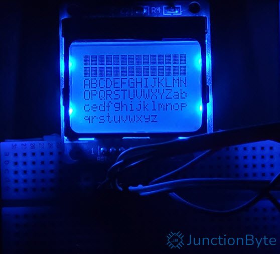
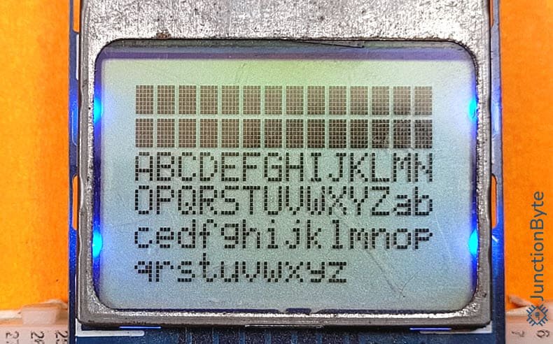
Using the previous Nokia 5110 LCD Driver code, we can modify the main.c file to control the Nokia 5110 LCD using the STM32G4 MCU. I created a small application where the LCD displays some basic graphics as well as some alphanumeric characters.
/* USER CODE BEGIN Header */
/**
  ******************************************************************************
  * @file           : main.c
  * @brief          : Main program body
  ******************************************************************************
  ******************************************************************************
  */
/* USER CODE END Header */
/* Includes ------------------------------------------------------------------*/
#include "main.h"

/* Private includes ----------------------------------------------------------*/
/* USER CODE BEGIN Includes */
#include "NOKIA5110_LCD.h"

/* USER CODE END Includes */

/* Private typedef -----------------------------------------------------------*/
/* USER CODE BEGIN PTD */

/* USER CODE END PTD */

/* Private define ------------------------------------------------------------*/
/* USER CODE BEGIN PD */

/* USER CODE END PD */

/* Private macro -------------------------------------------------------------*/
/* USER CODE BEGIN PM */

/* USER CODE END PM */

/* Private variables ---------------------------------------------------------*/
SPI_HandleTypeDef hspi1;

/* USER CODE BEGIN PV */

/* USER CODE END PV */

/* Private function prototypes -----------------------------------------------*/
void SystemClock_Config(void);
static void MX_GPIO_Init(void);
static void MX_SPI1_Init(void);
/* USER CODE BEGIN PFP */

/* USER CODE END PFP */

/* Private user code ---------------------------------------------------------*/
/* USER CODE BEGIN 0 */

/* USER CODE END 0 */

/**
  * @brief  The application entry point.
  * @retval int
  */
int main(void)
{

  /* USER CODE BEGIN 1 */

  /* USER CODE END 1 */

  /* MCU Configuration--------------------------------------------------------*/

  /* Reset of all peripherals, Initializes the Flash interface and the Systick. */
  HAL_Init();

  /* USER CODE BEGIN Init */

  /* USER CODE END Init */

  /* Configure the system clock */
  SystemClock_Config();

  /* USER CODE BEGIN SysInit */

  /* USER CODE END SysInit */

  /* Initialize all configured peripherals */
  MX_GPIO_Init();
  MX_SPI1_Init();
  /* USER CODE BEGIN 2 */
  /* Initialize the Nokia 5110 LCD */
  Nokia5110_Init(&hspi1);

  /* Set LCD contrast (modify the value based on your module) */
  Nokia5110_SetContrast(0x39);

  Nokia5110_SetBacklight(1);

  /* Graphics demonstration */
  Nokia5110_ClearBuffer();
  /* Draw a diagonal line from the top-left to the bottom-right */
  Nokia5110_DrawLine(0, 0, NOKIA5110_WIDTH - 1, NOKIA5110_HEIGHT - 1, 1);
  /* Draw a rectangle in the center */
  Nokia5110_DrawRect(10, 10, 64, 28, 1);
  /* Draw a filled rectangle in the top area */
  Nokia5110_FillRect(5, 5, 10, 5, 1);

  /* Update the display with the frame buffer contents */
  Nokia5110_Update();
  HAL_Delay(2000);
  Nokia5110_SetBacklight(0);
  Nokia5110_Clear();
  Nokia5110_ClearBuffer();
  Nokia5110_SetCursor(0, 0);
  Nokia5110_WriteString("ABCDEFGHIJKLMNOPQRSTUVWXYZ");

  /* USER CODE END 2 */

  /* Infinite loop */
  /* USER CODE BEGIN WHILE */
  while (1)
  {
    /* USER CODE END WHILE */

    /* USER CODE BEGIN 3 */
  }
  /* USER CODE END 3 */
}

/**
  * @brief System Clock Configuration
  * @retval None
  */
void SystemClock_Config(void)
{
  RCC_OscInitTypeDef RCC_OscInitStruct = {0};
  RCC_ClkInitTypeDef RCC_ClkInitStruct = {0};

  /** Configure the main internal regulator output voltage
  */
  HAL_PWREx_ControlVoltageScaling(PWR_REGULATOR_VOLTAGE_SCALE1_BOOST);

  /** Initializes the RCC Oscillators according to the specified parameters
  * in the RCC_OscInitTypeDef structure.
  */
  RCC_OscInitStruct.OscillatorType = RCC_OSCILLATORTYPE_HSE;
  RCC_OscInitStruct.HSEState = RCC_HSE_ON;
  RCC_OscInitStruct.PLL.PLLState = RCC_PLL_ON;
  RCC_OscInitStruct.PLL.PLLSource = RCC_PLLSOURCE_HSE;
  RCC_OscInitStruct.PLL.PLLM = RCC_PLLM_DIV2;
  RCC_OscInitStruct.PLL.PLLN = 85;
  RCC_OscInitStruct.PLL.PLLP = RCC_PLLP_DIV2;
  RCC_OscInitStruct.PLL.PLLQ = RCC_PLLQ_DIV2;
  RCC_OscInitStruct.PLL.PLLR = RCC_PLLR_DIV2;
  if (HAL_RCC_OscConfig(&RCC_OscInitStruct) != HAL_OK)
  {
    Error_Handler();
  }

  /** Initializes the CPU, AHB and APB buses clocks
  */
  RCC_ClkInitStruct.ClockType = RCC_CLOCKTYPE_HCLK|RCC_CLOCKTYPE_SYSCLK
                              |RCC_CLOCKTYPE_PCLK1|RCC_CLOCKTYPE_PCLK2;
  RCC_ClkInitStruct.SYSCLKSource = RCC_SYSCLKSOURCE_PLLCLK;
  RCC_ClkInitStruct.AHBCLKDivider = RCC_SYSCLK_DIV1;
  RCC_ClkInitStruct.APB1CLKDivider = RCC_HCLK_DIV1;
  RCC_ClkInitStruct.APB2CLKDivider = RCC_HCLK_DIV1;

  if (HAL_RCC_ClockConfig(&RCC_ClkInitStruct, FLASH_LATENCY_4) != HAL_OK)
  {
    Error_Handler();
  }
}

/**
  * @brief SPI1 Initialization Function
  * @param None
  * @retval None
  */
static void MX_SPI1_Init(void)
{

  /* USER CODE BEGIN SPI1_Init 0 */

  /* USER CODE END SPI1_Init 0 */

  /* USER CODE BEGIN SPI1_Init 1 */

  /* USER CODE END SPI1_Init 1 */
  /* SPI1 parameter configuration*/
  hspi1.Instance = SPI1;
  hspi1.Init.Mode = SPI_MODE_MASTER;
  hspi1.Init.Direction = SPI_DIRECTION_2LINES;
  hspi1.Init.DataSize = SPI_DATASIZE_8BIT;
  hspi1.Init.CLKPolarity = SPI_POLARITY_LOW;
  hspi1.Init.CLKPhase = SPI_PHASE_1EDGE;
  hspi1.Init.NSS = SPI_NSS_SOFT;
  hspi1.Init.BaudRatePrescaler = SPI_BAUDRATEPRESCALER_32;
  hspi1.Init.FirstBit = SPI_FIRSTBIT_MSB;
  hspi1.Init.TIMode = SPI_TIMODE_DISABLE;
  hspi1.Init.CRCCalculation = SPI_CRCCALCULATION_DISABLE;
  hspi1.Init.CRCPolynomial = 7;
  hspi1.Init.CRCLength = SPI_CRC_LENGTH_DATASIZE;
  hspi1.Init.NSSPMode = SPI_NSS_PULSE_ENABLE;
  if (HAL_SPI_Init(&hspi1) != HAL_OK)
  {
    Error_Handler();
  }
  /* USER CODE BEGIN SPI1_Init 2 */

  /* USER CODE END SPI1_Init 2 */

}

/**
  * @brief GPIO Initialization Function
  * @param None
  * @retval None
  */
static void MX_GPIO_Init(void)
{
  GPIO_InitTypeDef GPIO_InitStruct = {0};
  /* USER CODE BEGIN MX_GPIO_Init_1 */

  /* USER CODE END MX_GPIO_Init_1 */

  /* GPIO Ports Clock Enable */
  __HAL_RCC_GPIOF_CLK_ENABLE();
  __HAL_RCC_GPIOA_CLK_ENABLE();

  /*Configure GPIO pin Output Level */
  HAL_GPIO_WritePin(GPIOA, NOKIA5110_BL_Pin|NOKIA5110_DC_Pin|NOKIA5110_CE_Pin|NOKIA5110_RST_Pin, GPIO_PIN_RESET);

  /*Configure GPIO pins : NOKIA5110_BL_Pin NOKIA5110_DC_Pin NOKIA5110_CE_Pin NOKIA5110_RST_Pin */
  GPIO_InitStruct.Pin = NOKIA5110_BL_Pin|NOKIA5110_DC_Pin|NOKIA5110_CE_Pin|NOKIA5110_RST_Pin;
  GPIO_InitStruct.Mode = GPIO_MODE_OUTPUT_PP;
  GPIO_InitStruct.Pull = GPIO_NOPULL;
  GPIO_InitStruct.Speed = GPIO_SPEED_FREQ_LOW;
  HAL_GPIO_Init(GPIOA, &GPIO_InitStruct);

  /* USER CODE BEGIN MX_GPIO_Init_2 */

  /* USER CODE END MX_GPIO_Init_2 */
}

/* USER CODE BEGIN 4 */

/* USER CODE END 4 */

/**
  * @brief  This function is executed in case of error occurrence.
  * @retval None
  */
void Error_Handler(void)
{
  /* USER CODE BEGIN Error_Handler_Debug */
  /* User can add his own implementation to report the HAL error return state */
  __disable_irq();
  while (1)
  {
  }
  /* USER CODE END Error_Handler_Debug */
}

#ifdef  USE_FULL_ASSERT
/**
  * @brief  Reports the name of the source file and the source line number
  *         where the assert_param error has occurred.
  * @param  file: pointer to the source file name
  * @param  line: assert_param error line source number
  * @retval None
  */
void assert_failed(uint8_t *file, uint32_t line)
{
  /* USER CODE BEGIN 6 */
  /* User can add his own implementation to report the file name and line number,
     ex: printf("Wrong parameters value: file %s on line %d\r\n", file, line) */
  /* USER CODE END 6 */
}
#endif /* USE_FULL_ASSERT */
You can use the driver to create even more complex applications such as displaying a menu system, bitmap images, and more.
Conclusion
A simple beginner-friendly tutorial on how to interface Nokia 5110 LCD with STM32G4 MCU. In this guide, we learned the basics of Nokia 5110 LCD and the corresponding PCD8544 LCD Controller. Later, we saw how to configure the STM32CubeIDE for all the peripheral and clock.
Then there is the driver code for the Nokia 5110 LCD. This driver makes use of the STM32 HAL framework so it works seamlessly with any STM32 Microcontroller. Last but not least, I gave a sample application code that demonstrates some capabilities of the driver.
You can further improve the driver code to add a lot more complex graphics-related functions. If you are interested, I can add some more applications as well. Also, if you have any difficulty understanding any part of this guide (configuration or driver), do let me know in the comments section. I will try to respond with a solution.
thanks!