Everything has a touch interface nowadays. From everyday essentials such as mobile phones to unnecessary things like the stereo and A/C controls in cars, all use capacitive touch to accept input. While this trend looks “cool,” it lacks the important tactile feedback. Another way to accept user input without losing the “tactile” feel is matrix keypads. The 4×4 Matrix Keypad, in particular, is one of the simplest yet widely popular input devices in several embedded applications. In this guide, let us learn how to interface a 4×4 matrix keypad with STM32G4 MCU (specifically the STM32G431CBU6).
We can use UART to display the key-press action. Since I already worked on interfacing an I2C LCD with STM32G4, I will be using that to show the characters corresponding to each key of the 4×4 matrix keypad.
First, I will explain a little bit about the working of a typical matrix keypad and how it reduces the no. of GPIO pins of a microcontroller (when compared to regular push buttons or switches). Later, I will explain how to configure the STM32CubeIDE and generate the base code. Then we will move on to writing the driver for the matrix keypad that works with the STM32 HAL architecture. Last but not least, I will show a demo application where I will display the keypress on a I2C 16×2 LCD.
Components Needed
Hardware
- STM32G431CBU6-based board (I will be using the WeAct Studios STM32G431 Core Board)
- 4×4 Matrix Keypad
- 16×2 LCD with PCF8574 I2C (I2C) Adapter
- Jumper wires
- Breadboard (optional)
Software
- STM32CubeIDE
Before starting the project, gather the required hardware components and install the necessary software on your computer.
For the hardware, start with an STM32G431CBU6-based development board. I already talked about this in my previous guides that the WeAct Studios’ STM32G431 Core Board is a very good low-cost development platform for the STM32G4 series of MCUs. You don’t need any additional hardware for programming as it supports USB DFU (where you can easily upload the firmware using a USB-C Cable).
If you are feeling fancy, then you can go with the official ST route with the Nucleo-G431KB board. While it is slightly more expensive than the WeAct Board, it has an on-board ST-LINK debugger.
Next, is the 4×4 matrix keypad. This keypad contains 16 individual switches arranged in rows and columns. It typically comes with a 8-pin header that connects to a microcontroller. You can get 4×4 Matrix Keypads either with tactile buttons or membrane keypad.
For output monitoring, we can use a 16×2 LCD with PCF8574 I2C Adapter. This combination reduces the GPIO pins to only two.
You need some male-to-male jumper wires to link the keypad to the MCU board. A breadboard can simplify the entire assembly (though not necessary).
On the software side, all you need is to install the STM32CubeIDE. It supports code generation, compiling, and debugging in one platform.
Understanding the 4×4 Matrix Keypad
Keypad Architecture
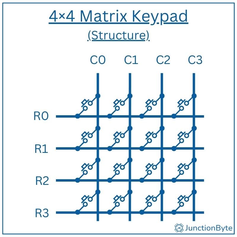
A 4×4 matrix keypad consists of a grid layout with 4 rows and 4 columns. This structure has 16 keys (buttons or switches) in a space-efficient format. Each key sits at the intersection of a unique row and column. When we press a key, it connects one specific row to one specific column.
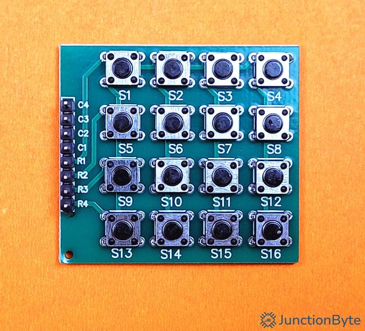
Matrix keypads provide a simple mechanical interface for user input. Their grid-based structure supports several input keys (16 in case of a 4×4 Matrix) without using too many GPIO pins (as compared to individual switches).
As I said before, the matrix keypad can be made up of either push buttons or a membrane keypad where the internal contacts are made from conductive materials. These switches/contacts remain open until someone presses a button. When a key gets pressed, it creates a closed path between one row line and one column line and thus current flows through a defined circuit.
Key Scanning Technique
The most common way to detect which key has been pressed is to implement a scanning technique in the firmware. Here’s the brief overview of the scanning logic: during each cycle, the system (in this case, the STM32G4 MCU) pulls a single column line low while keeping the others high. At the same moment, it reads the voltage level on all four row lines one-by-one.
If a key connects the active column to any row, that row line reads a LOW level. The firmware then identifies the key’s position by matching the active column and the LOW row. By repeating this cycle for all columns, the code can identify which key is currently pressed. This scanning process happens fast enough to seem instantaneous to the user.
Key Mapping
Since the keypad does not send any data to the microcontroller (as it is essentially a passive grid of switches), we can assign each combination of row and column to represent one unique character. This process is known as Key Mapping.
In this, we define which character corresponds to each row-column pair. The most common layout follows a telephone-style arrangement. The first three rows contain numbers and symbols: 1 2 3, 4 5 6, and 7 8 9. The fourth row includes * 0 #. The last column of each row is usually labeled A, B, C, and D.
We can customize the mapping in firmware based on project needs. For example, you might assign A to “Enter” or D to “Backspace.” The mapping table stays inside the source code and does not depend on the hardware layout.
Project Setup in STM32CubeIDE
The next step is to create a project in the STM32CubeIDE and configure the MCU as per our needs. Start by opening STM32CubeIDE. Once the IDE launches, select “File” from the top menu, then click “New” and select “STM32 Project.” A new dialog window will appear with microcontroller options.
Type “STM32G431CBU6” into the MCU selector search bar (top left) and select the same from the results on the right. After the selection, click “Next” and enter a name for the project. Pick a location for storage and you can keep the rest of the options at their default.
Once the IDE finishes creating the project, it opens a “Device Configuration” tool, a graphical interface that displays the chip’s package layout with labeled pins.
GPIO Configuration
We will start with the basics. Expand the “System Core” section on the left and click on “RCC.” Set the “High Speed Clock (HSE)” to “Crystal/Ceramic Resonator” as the WeAct STM32G431 Board has an 8MHz Crystal. Move to the “SYS” option in the “System Core” and set the “Debug” as “Serial Wire.”
Next, we have to assign eight GPIOs for the keypad, four pins for the rows and four for the columns. In the case of WeAct Studios STM32G431 Core Board, GPIO Pins PA0 through PA7 are free. Let us use these pins for rows (PA0 – PA3) and columns (PA4 – PA7).
Assign the row pins as inputs and column pins as outputs. Enter appropriate labels to these pins (ROW0, ROW1, ROW2, ROW3, COL0, COL1, COL2, and COL3). While we can leave things here, there is one more step you can follow to make things a little bit better.
For all the row pins, we can set the input mode with internal pull-up resistors enabled. These resistors keep the input pins at a HIGH logic level when idle (key no presses). They allow the pin to read LOW only when pressed. Without pull-up resistors, floating inputs might cause false readings.
To do this, select the “GPIO” option under “System Core” on the left, click on the row pins (in this case, PA0 – PA3), and set “GPIO Pull-up/Pull-down” to “Pull-up.”
You can leave the column pins at their default output push-pull mode. Push-pull mode supports both HIGH and LOW output states (however, we will configure the firmware to drive each column pin LOW during scanning cycles).
I2C Configuration
Since I will be using a PCF8574 I2C LCD to monitor the output, I need to enable the I2C peripheral. Expand “Connectivity” in the left panel and expand the “I2C1” option. Enable “I2C1” by selecting “I2C” mode from the list.
STM32CubeIDE automatically assigns PA15 as I2C1_SCL and PB7 as I2C1_SDA. In the “Configuration” section, confirm that the “I2C Speed Mode” is set to “Standard Mode” and the “I2C Speed Frequency” is “100KHz.” You can leave the remaining parameters at their default values.
Clock Configuration
While we have hinted to the STM32CubeIDE that there is an external crystal that can supply clock signal to the MCU, we haven’t configured it yet. Let us do that now by clicking on the “Clock Configuration” tab.
Select “HSE” as the primary clock source (for PLL Source Mux) and “PLLCLK” for System Clock Mux. If you want maximum MCU performance, we have to make sure that the System Clock (SYSCLK) runs at 170 MHz. For this, set the “HCLK” value as 170 (MHz) and hit enter. The IDE will automatically adjust different parameters and set the SYSCLK as 170 MHz.
Generate Project Code
After completing all configurations, save the Device Configuration options by pressing “Ctrl+s” and the IDE will ask whether to generate code or not. Click on “Yes.” The IDE will now ask whether to switch to C/C++ perspective and once again, click on “Yes.”
Alternatively, you can select Project -> Generate Code to generate the code.
How to Develop the 4×4 Matrix Keypad Driver?
We know that a 4×4 matrix keypad has 4 rows and 4 columns i.e., a total of 16 keys. Each key connects a row to a column. Keys are arranged like this (example layout):
     COL0   COL1   COL2   COL3
    ---------------------------
ROW0 |  '1' | '2' | '3' | 'A' |
ROW1 |  '4' | '5' | '6' | 'B' |
ROW2 |  '7' | '8' | '9' | 'C' |
ROW3 |  '*' | '0' | '#' | 'D' |
When we press a key, it electrically connects one row and one column. For example, if we press Key ‘5’: it connects ROW1 with COL1.
The heart of the driver is the scanning logic of Keypad_GetKey() function. We want to find out which key is pressed. However, we can’t read all keys at once because of shared lines. So, we need to scan the matrix by driving columns one at a time and reading rows.
Scanning Logic
Here’s a step-by-step logic for scanning the keys:
We configured all the row pins as inputs with pull-ups and column pins as outputs (you can change this as per your requirement). Set the initial state of all column pins to logic HIGH. This prevents accidental key detection during startup.
In the scanning loop, activate one column pin at a time. Pull the selected column pin to logic LOW and keep the other columns HIGH. This method isolates a single column for testing.
for (col = 0; col < 4; col++) {
    // Set current col LOW
    ...
    // row detection logic
    ...
    // Set current col back HIGH
    ...
}
Next, read the row inputs while one column stays LOW. If a user presses a key, a row pin connected to that column reads LOW.
/* Read all rows */
for (row = 0; row < KEYPAD_ROWS; row++) {
  if (HAL_GPIO_ReadPin(ROW_GPIO_PORT, ROW_PIN) == GPIO_PIN_RESET)
  {
    // Key at [row][col] is being pressed
    ...
Use the current row and col index to lookup the actual character:
/* Return mapped character */
return keymap[row][col];
After reading all rows, set the current column HIGH again. Repeat this scanning process for each of the four columns. Scan all columns quickly enough to detect key presses without delay. Use a short delay between each column scan to allow signal settling. This step improves consistency in key detection.
/* Wait until key is released (simple debounce) */
while (HAL_GPIO_ReadPin(ROW_PORT[row], ROW_PIN[row]) == GPIO_PIN_RESET) { }
HAL_Delay(10);
4×4 Matrix Keypad Driver for STM32G4
In the “Project Explorer”, right-click the “Drivers” folder and add a folder (New -> Folder). This folder will hold all the driver files that we wrote and not from ST. I named this “User_Driver” but you can name it as you wish as long as it is clear. Right-click this new folder (User_Driver) and add two more folders with names “Inc” and “Src.” The “Inc” folder will contain the header files of the driver while the “Src” folder will contain the actual source files.
4×4 Matrix Keypad Driver Header Code
Right-click the “Inc” folder and add a new header file (New -> Header File) and give it the name “Matrix_Keypad.h” (don’t forget the .h extension).
Delete any auto-generated data, copy and paste the following code, and save the file. I have added comments for all the sections for easy understanding.
/**
  ******************************************************************************
  * @file    Matrix_Keypad.h
  * @brief   Header file for 4x4 Matrix Keypad driver.
  ******************************************************************************
  */

/* Define to prevent recursive inclusion -------------------------------------*/
#ifndef __MATRIX_KEYPAD_H_
#define __MATRIX_KEYPAD_H_

#include "stm32g4xx_hal.h"

/* Number of rows and columns */
#define KEYPAD_ROWS    4
#define KEYPAD_COLS    4

/* Pin definitions: alter these to match your PCB */
/* Rows */
#define ROW0_GPIO_Port GPIOA
#define ROW0_Pin       GPIO_PIN_0
#define ROW1_GPIO_Port GPIOA
#define ROW1_Pin       GPIO_PIN_1
#define ROW2_GPIO_Port GPIOA
#define ROW2_Pin       GPIO_PIN_2
#define ROW3_GPIO_Port GPIOA
#define ROW3_Pin       GPIO_PIN_3

/* Columns */
#define COL0_GPIO_Port GPIOA
#define COL0_Pin       GPIO_PIN_4
#define COL1_GPIO_Port GPIOA
#define COL1_Pin       GPIO_PIN_5
#define COL2_GPIO_Port GPIOA
#define COL2_Pin       GPIO_PIN_6
#define COL3_GPIO_Port GPIOA
#define COL3_Pin       GPIO_PIN_7

#ifdef __cplusplus
extern "C" {
#endif

/* Key labeling according to row/column index */
static const char keymap[KEYPAD_ROWS][KEYPAD_COLS] = {
    { '1', '2', '3', 'A' },
    { '4', '5', '6', 'B' },
    { '7', '8', '9', 'C' },
    { '*', '0', '#', 'D' }
};

/**
  * @brief  Initialize the GPIOs for 4×4 keypad scanning.
  *         Rows are Inputs with pull-ups.
  *         Columns are Outputs (push-pull), HIGH by default.
  * @param  None
  * @retval None
  */
void Keypad_Init(void);

/**
  * @brief  Scan the keypad and return the first pressed key.
  * @param  None
  * @retval ASCII character of the key ('0'–'9','A'–'D','*','#')
  *         Returns '\0' if no key is pressed.
  */
char Keypad_GetKey(void);

#ifdef __cplusplus
}
#endif

#endif /* __MATRIX_KEYPAD_H_ */
MAX7219 LED Matrix Driver Source Code
Next, create a “Matrix_Keypad.c” file in the Src folder (this time, create a Source File i.e., New -> Source File). Copy and paste the following driver code in this file and save it.
/**
  ******************************************************************************
  * @file    Matrix_Keypad.c
  * @brief   Source file for 4x4 Matrix Keypad driver.
  ******************************************************************************
  */

/* Includes ------------------------------------------------------------------*/
#include "Matrix_Keypad.h"

/* Map rows/columns to arrays for easy iteration */
static GPIO_TypeDef* const ROW_PORT[KEYPAD_ROWS] = {
    ROW0_GPIO_Port, ROW1_GPIO_Port, ROW2_GPIO_Port, ROW3_GPIO_Port
};
static const uint16_t ROW_PIN[KEYPAD_ROWS] = {
    ROW0_Pin, ROW1_Pin, ROW2_Pin, ROW3_Pin
};

static GPIO_TypeDef* const COL_PORT[KEYPAD_COLS] = {
    COL0_GPIO_Port, COL1_GPIO_Port, COL2_GPIO_Port, COL3_GPIO_Port
};
static const uint16_t COL_PIN[KEYPAD_COLS] = {
    COL0_Pin, COL1_Pin, COL2_Pin, COL3_Pin
};

/**
  * @brief  Initialize the GPIOs for 4×4 keypad scanning.
  *         Rows are Inputs with pull-up resistors.
  *         Columns are Outputs (push-pull).
  * @param  None
  * @retval None
  */
void Keypad_Init(void)
{
  uint8_t i = 0;
  for (i = 0; i < KEYPAD_COLS; i++)
  {
	  /* Drive col high (inactive) */
	HAL_GPIO_WritePin(COL_PORT[i], COL_PIN[i], GPIO_PIN_SET);
  }
}

/**
  * @brief  Scan the keypad and return the first pressed key.
  * @param  None
  * @retval ASCII character of the key ('0'–'9','A'–'D','*','#')
  *         Returns '\0' if no key is pressed.
  */
char Keypad_GetKey(void)
{
  uint8_t row, col;

  /* Scan each col */
  for (col = 0; col < KEYPAD_COLS; col++)
  {
    /* Activate this col by pulling it low */
    HAL_GPIO_WritePin(COL_PORT[col], COL_PIN[col], GPIO_PIN_RESET);
    /* Small delay to allow signals to settle */
    HAL_Delay(1);

    /* Read all rows */
    for (row = 0; row < KEYPAD_ROWS; row++)
    {
      if (HAL_GPIO_ReadPin(ROW_PORT[row], ROW_PIN[row]) == GPIO_PIN_RESET)
      {
        /* Wait until key is released (simple debounce) */
        while (HAL_GPIO_ReadPin(ROW_PORT[row], ROW_PIN[row]) == GPIO_PIN_RESET) { }
        HAL_Delay(10);
        /* Deactivate col */
        HAL_GPIO_WritePin(COL_PORT[col], COL_PIN[col], GPIO_PIN_SET);
        /* Return mapped character */
        return keymap[row][col];
      }
    }
    /* Deactivate col before next iteration */
    HAL_GPIO_WritePin(COL_PORT[col], COL_PIN[col], GPIO_PIN_SET);
  }
  /* No key pressed */
  return '\0';
}
PCF8574 I2C LCD Driver
If you followed my previous guide on how to interface a PCF8574 I2C LCD with STM32G4, then you will remember that I implemented a complete driver for the PCF8574 I2C Module that works with a typical 16×2 LCD.
So, the next step would be to add those files as well. Follow the same process for adding the header and source files (PCF8574_LCD.h and PCF8574_LCD.c). You can get the code for these driver files from this guide: How to Interface PCF8574 I2C LCD with STM32G4.
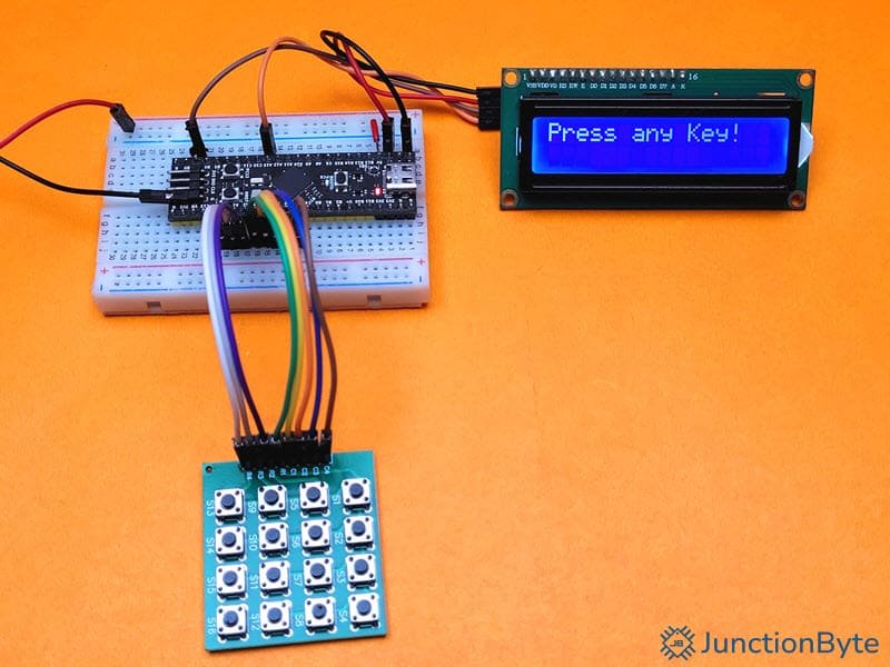
Demo Code to Interface 4×4 Matrix Keypad with STM32G4
We can now use these driver files and create a simple application that will interface a 4×4 matrix keypad with STM32G4 MCU, detect the keypressed, and display the result on an I2C LCD Module. Here’s the code for your reference. You can replace the code in the “main.c” file generated by the STM32CubeIDE with this code.
/* USER CODE BEGIN Header */
/**
  ******************************************************************************
  * @file           : main.c
  * @brief          : Main program body
  ******************************************************************************
  ******************************************************************************
  */
/* USER CODE END Header */
/* Includes ------------------------------------------------------------------*/
#include "main.h"

/* Private includes ----------------------------------------------------------*/
/* USER CODE BEGIN Includes */
#include "PCF8574_LCD.h"
#include "Matrix_Keypad.h"

/* USER CODE END Includes */

/* Private typedef -----------------------------------------------------------*/
/* USER CODE BEGIN PTD */

/* USER CODE END PTD */

/* Private define ------------------------------------------------------------*/
/* USER CODE BEGIN PD */

/* USER CODE END PD */

/* Private macro -------------------------------------------------------------*/
/* USER CODE BEGIN PM */

/* USER CODE END PM */

/* Private variables ---------------------------------------------------------*/
I2C_HandleTypeDef hi2c1;

/* USER CODE BEGIN PV */
/* Create LCD handle */
PCF8574_LCD_HandleTypeDef lcd;

/* USER CODE END PV */

/* Private function prototypes -----------------------------------------------*/
void SystemClock_Config(void);
static void MX_GPIO_Init(void);
static void MX_I2C1_Init(void);
/* USER CODE BEGIN PFP */

/* USER CODE END PFP */

/* Private user code ---------------------------------------------------------*/
/* USER CODE BEGIN 0 */

/* USER CODE END 0 */

/**
  * @brief  The application entry point.
  * @retval int
  */
int main(void)
{
  /* USER CODE BEGIN 1 */
	char key;

  /* USER CODE END 1 */

  /* MCU Configuration--------------------------------------------------------*/

  /* Reset of all peripherals, Initializes the Flash interface and the Systick. */
  HAL_Init();

  /* USER CODE BEGIN Init */

  /* USER CODE END Init */

  /* Configure the system clock */
  SystemClock_Config();

  /* USER CODE BEGIN SysInit */

  /* USER CODE END SysInit */

  /* Initialize all configured peripherals */
  MX_GPIO_Init();
  MX_I2C1_Init();
  /* USER CODE BEGIN 2 */

  Keypad_Init();
  /* Set up LCD handle */
  lcd.hi2c = &hi2c1;
  lcd.address = 0x3F; /* Common I2C address. Change if needed.*/
  /* Initialize LCD */
  LCD_Init(&lcd);
  LCD_Backlight(&lcd, 1); // Turn backlight on

  /* Display a message */
  LCD_SetCursor(&lcd, 0, 0);
  LCD_Print(&lcd, "Press any Key!");

  /* USER CODE END 2 */

  /* Infinite loop */
  /* USER CODE BEGIN WHILE */
  while (1)
  {
    /* USER CODE END WHILE */

    /* USER CODE BEGIN 3 */
    key = Keypad_GetKey();
    if (key != '\0')
    {
      LCD_Clear(&lcd);
      LCD_SetCursor(&lcd, 0, 0);
      LCD_Print(&lcd, "Key Pressed: ");
      LCD_WriteChar(&lcd, key);
      HAL_Delay(50);
    }
  }
  /* USER CODE END 3 */
}

/**
  * @brief System Clock Configuration
  * @retval None
  */
void SystemClock_Config(void)
{
  RCC_OscInitTypeDef RCC_OscInitStruct = {0};
  RCC_ClkInitTypeDef RCC_ClkInitStruct = {0};

  /** Configure the main internal regulator output voltage
  */
  HAL_PWREx_ControlVoltageScaling(PWR_REGULATOR_VOLTAGE_SCALE1_BOOST);

  /** Initializes the RCC Oscillators according to the specified parameters
  * in the RCC_OscInitTypeDef structure.
  */
  RCC_OscInitStruct.OscillatorType = RCC_OSCILLATORTYPE_HSE;
  RCC_OscInitStruct.HSEState = RCC_HSE_ON;
  RCC_OscInitStruct.PLL.PLLState = RCC_PLL_ON;
  RCC_OscInitStruct.PLL.PLLSource = RCC_PLLSOURCE_HSE;
  RCC_OscInitStruct.PLL.PLLM = RCC_PLLM_DIV2;
  RCC_OscInitStruct.PLL.PLLN = 85;
  RCC_OscInitStruct.PLL.PLLP = RCC_PLLP_DIV2;
  RCC_OscInitStruct.PLL.PLLQ = RCC_PLLQ_DIV2;
  RCC_OscInitStruct.PLL.PLLR = RCC_PLLR_DIV2;
  if (HAL_RCC_OscConfig(&RCC_OscInitStruct) != HAL_OK)
  {
    Error_Handler();
  }

  /** Initializes the CPU, AHB and APB buses clocks
  */
  RCC_ClkInitStruct.ClockType = RCC_CLOCKTYPE_HCLK|RCC_CLOCKTYPE_SYSCLK
                              |RCC_CLOCKTYPE_PCLK1|RCC_CLOCKTYPE_PCLK2;
  RCC_ClkInitStruct.SYSCLKSource = RCC_SYSCLKSOURCE_PLLCLK;
  RCC_ClkInitStruct.AHBCLKDivider = RCC_SYSCLK_DIV1;
  RCC_ClkInitStruct.APB1CLKDivider = RCC_HCLK_DIV1;
  RCC_ClkInitStruct.APB2CLKDivider = RCC_HCLK_DIV1;

  if (HAL_RCC_ClockConfig(&RCC_ClkInitStruct, FLASH_LATENCY_4) != HAL_OK)
  {
    Error_Handler();
  }
}

/**
  * @brief I2C1 Initialization Function
  * @param None
  * @retval None
  */
static void MX_I2C1_Init(void)
{

  /* USER CODE BEGIN I2C1_Init 0 */

  /* USER CODE END I2C1_Init 0 */

  /* USER CODE BEGIN I2C1_Init 1 */

  /* USER CODE END I2C1_Init 1 */
  hi2c1.Instance = I2C1;
  hi2c1.Init.Timing = 0x40B285C2;
  hi2c1.Init.OwnAddress1 = 0;
  hi2c1.Init.AddressingMode = I2C_ADDRESSINGMODE_7BIT;
  hi2c1.Init.DualAddressMode = I2C_DUALADDRESS_DISABLE;
  hi2c1.Init.OwnAddress2 = 0;
  hi2c1.Init.OwnAddress2Masks = I2C_OA2_NOMASK;
  hi2c1.Init.GeneralCallMode = I2C_GENERALCALL_DISABLE;
  hi2c1.Init.NoStretchMode = I2C_NOSTRETCH_DISABLE;
  if (HAL_I2C_Init(&hi2c1) != HAL_OK)
  {
    Error_Handler();
  }

  /** Configure Analogue filter
  */
  if (HAL_I2CEx_ConfigAnalogFilter(&hi2c1, I2C_ANALOGFILTER_ENABLE) != HAL_OK)
  {
    Error_Handler();
  }

  /** Configure Digital filter
  */
  if (HAL_I2CEx_ConfigDigitalFilter(&hi2c1, 0) != HAL_OK)
  {
    Error_Handler();
  }
  /* USER CODE BEGIN I2C1_Init 2 */

  /* USER CODE END I2C1_Init 2 */

}

/**
  * @brief GPIO Initialization Function
  * @param None
  * @retval None
  */
static void MX_GPIO_Init(void)
{
  GPIO_InitTypeDef GPIO_InitStruct = {0};
  /* USER CODE BEGIN MX_GPIO_Init_1 */

  /* USER CODE END MX_GPIO_Init_1 */

  /* GPIO Ports Clock Enable */
  __HAL_RCC_GPIOF_CLK_ENABLE();
  __HAL_RCC_GPIOA_CLK_ENABLE();
  __HAL_RCC_GPIOB_CLK_ENABLE();

  /*Configure GPIO pin Output Level */
  HAL_GPIO_WritePin(GPIOA, COL0_Pin|COL1_Pin|COL2_Pin|COL3_Pin, GPIO_PIN_RESET);

  /*Configure GPIO pins : ROW0_Pin ROW1_Pin ROW2_Pin ROW3_Pin */
  GPIO_InitStruct.Pin = ROW0_Pin|ROW1_Pin|ROW2_Pin|ROW3_Pin;
  GPIO_InitStruct.Mode = GPIO_MODE_INPUT;
  GPIO_InitStruct.Pull = GPIO_PULLUP;
  HAL_GPIO_Init(GPIOA, &GPIO_InitStruct);

  /*Configure GPIO pins : COL0_Pin COL1_Pin COL2_Pin COL3_Pin */
  GPIO_InitStruct.Pin = COL0_Pin|COL1_Pin|COL2_Pin|COL3_Pin;
  GPIO_InitStruct.Mode = GPIO_MODE_OUTPUT_PP;
  GPIO_InitStruct.Pull = GPIO_NOPULL;
  GPIO_InitStruct.Speed = GPIO_SPEED_FREQ_LOW;
  HAL_GPIO_Init(GPIOA, &GPIO_InitStruct);

  /* USER CODE BEGIN MX_GPIO_Init_2 */

  /* USER CODE END MX_GPIO_Init_2 */
}

/* USER CODE BEGIN 4 */

/* USER CODE END 4 */

/**
  * @brief  This function is executed in case of error occurrence.
  * @retval None
  */
void Error_Handler(void)
{
  /* USER CODE BEGIN Error_Handler_Debug */
  /* User can add his own implementation to report the HAL error return state */
  __disable_irq();
  while (1)
  {
  }
  /* USER CODE END Error_Handler_Debug */
}

#ifdef  USE_FULL_ASSERT
/**
  * @brief  Reports the name of the source file and the source line number
  *         where the assert_param error has occurred.
  * @param  file: pointer to the source file name
  * @param  line: assert_param error line source number
  * @retval None
  */
void assert_failed(uint8_t *file, uint32_t line)
{
  /* USER CODE BEGIN 6 */
  /* User can add his own implementation to report the file name and line number,
     ex: printf("Wrong parameters value: file %s on line %d\r\n", file, line) */
  /* USER CODE END 6 */
}
#endif /* USE_FULL_ASSERT */
I skipped the part on how to upload the code to the STM32G4 Microcontroller as I already discussed it in great detail in my previous guides.
Here’s the links to those guides:
Conclusion
This was a simple, beginner-friendly guide on how to interface a 4×4 Matrix Keypad with an STM32G4 MCU. In this guide, we saw the basics of a matrix keypad and how to implement the scanning logic. Later, I explained the steps you need to follow to write a driver for the 4×4 Matrix Keypad that will work with STM32G4 MCU using the STM32 HAL Architecture as a base.
To demonstrate the working of the driver, we then wrote a simple application that uses all the driver files to detect keypress and display the corresponding key value on the LCD.
The driver simply reads if the key is pressed or not and assigns the key a value from the pre-defined keymap. We can further extend the driver to detect double presses of the keys as well as long presses (press and hold).