Push Buttons are one of the simplest input devices in the world of embedded systems. But if you want to implement a better user interaction mechanism, then you might need more than one such button. This way, we can design the system to accept commands, passwords or pins, and numerical values. One of the easiest ways to do this is through Matrix Keypads. You will find such keypads in security systems, access control systems, industrial control panels, etc. So, in this guide, let us learn how to interface a 4×4 Matrix Keypad with an 8051 Microcontroller.
First, we will understand some basics of Matrix Keypads (hardware arrangement, working, and benefits). Then I will explain the logic we need to follow to scan the keys and decode the keypress. Last but not least, I will build a simple application where the 8051 Microcontroller controls a generic 4×4 Matrix Keypad, detects the keypress, and displays the result on UART and LCD.
As Matrix Keypads are nothing but a bunch of Push Buttons arranged in a special fashion, you can learn more about interfacing simple push buttons with the 8051 Microcontroller in this guide.
What is a Matrix Keypad?
A matrix keypad is a very useful input device that consists of multiple keys (switches or buttons) arranged in rows and columns. Unlike individual switches, which require separate connections for each button, a matrix keypad groups keys in a grid pattern. Most keypads use a flexible membrane or tactile push buttons for user input.
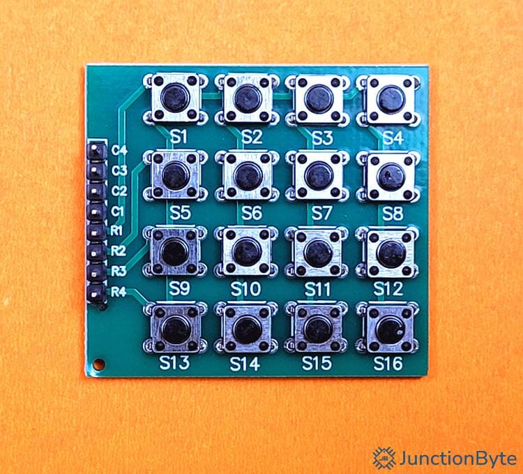
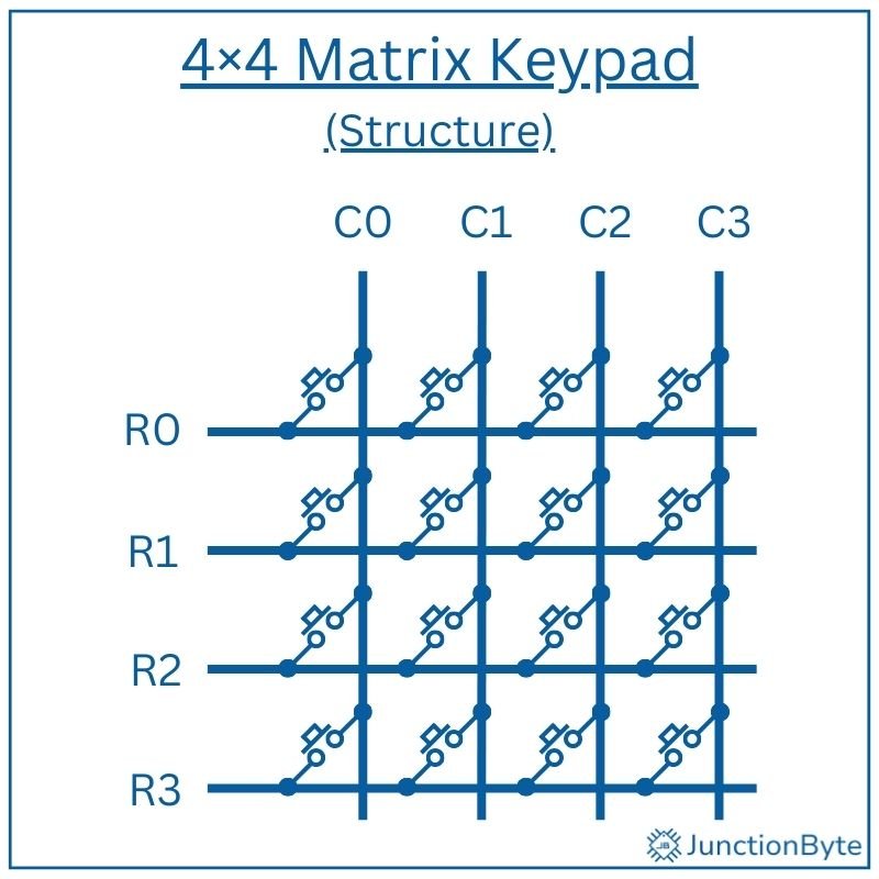
If you take a 4×4 keypad for example, it consists of four rows and four columns, forming a grid that supports up to 16 keys.
Each key in the matrix sits at the intersection of a row and a column. Pressing a key completes an electrical circuit between the corresponding row and column. This creates a unique connection point that the microcontroller can identify.
The design allows microcontrollers to detect key presses using fewer input/output (I/O) pins. We can also scale Matrix Keypads for larger applications, such as 8×8 keypads, without drastically increasing complexity (in terms of hardware or software).
How the Matrix Reduces the Number of I/O Pins Needed?
A matrix keypad requires fewer microcontroller pins compared to individual button connections. If a system uses separate I/O lines for each key, a 16-button keypad would need 16 I/O pins.
By arranging keys in a matrix, the keypad reduces the required connections significantly. A 4×4 matrix needs only eight I/O pins—four for rows and four for columns.
When the microcontroller activates one row at a time and checks the columns for a signal, it determines which key was pressed. No matter the size, smaller or larger keypads follow the same principle.
How Matrix Keypads Work?
A microcontroller detects key presses by systematically scanning the rows and reading the column states.
The scanning process begins by setting all rows as INPUTS while keeping all columns as OUTPUTS. The microcontroller scans the keypad by setting one row LOW at a time and checking the columns for a corresponding LOW signal to detect a connection. This process, known as multiplexing, allows the system to detect which key has been pressed by identifying the active row-column pair.
If no button is pressed, all columns remain in their default state. When a key is pressed, it establishes a path between the active row and a specific column and the microcontroller will detect this change.
By repeating this process for each row, the microcontroller can identify the exact location of the pressed key.
To complete the scanning cycle, the microcontroller resets the current row, activates the next row, and checks the columns again. This process continues in a loop so that the system can detect key presses in real time.
With faster scanning rates, we can improve the responsiveness of the system and make Matrix Keypads suitable for applications that require quick user input.
How Pressing a Key Creates a Connection Between a Specific Row and Column?
Pressing a button in a matrix keypad closes a switch/button between a row and a column. Each button contains two terminals; one connected to a row and the other to a column.
When the button remains unpressed, no electrical path exists between the row and column.
However, when a user presses a key, it completes the circuit between its assigned row and column. The microcontroller detects this connection by monitoring the column states during the scanning process.
If a column changes from HIGH to LOW, it identifies the corresponding row-column combination and determines which key was pressed.
Advantages of Matrix Keypads Over Regular Switches
- You Need Fewer Microcontroller Pins: Using a matrix keypad, we can minimize the number of I/O pins of a microcontroller. If we follow the traditional method, then we need a dedicated pin for each button. This becomes impractical as the number of keys increases. A simple 16-button keypad would need 16 microcontroller pins if wired individually. With matrix wiring, we can make the same 16-button keypad to work with only eight pins (four for rows and four for columns).
- Cost-Effective: Matrix keypads lower material costs by reducing the number of required wires and microcontroller connections. With fewer connections, the PCB layout becomes much simpler and there will be no risk of wiring errors.
- Simplicity in Design: We can easily integrate matrix keypads into systems that require multiple inputs without increasing design complexity. With software-based scanning, we can modify key mappings or add features without changing the hardware.
Hardware Setup: Connecting the 4×4 Matrix Keypad to 8051
Components Needed
- 4×4 Matrix Keypad
- 8051 Microcontroller (preferably a Development Board based on 8051)
- Connecting Wires
- Breadboard
Circuit Connections
A 4×4 matrix keypad typically has 8 pins, with 4 dedicated to rows (R1–R4) and 4 to columns (C1–C4). Each row and column corresponds to a specific line in the grid.
To interface the keypad with the 8051 microcontroller, we must connect the rows and columns to specific I/O ports. For instance, we can link the rows R1 – R4 to Port Pins P1.0 – P1.3 and configure these Port Pins as INPUTS.
Similarly, we can link the columns C1 – C4 to Port Pins P2.0 – P2.3 and set them as OUTPUTS.
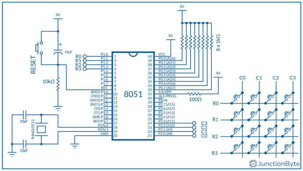
Circuit Diagram
The following image shows the complete circuit diagram for interfacing a 4×4 Matrix Keypad with an 8051 Microcontroller. Depending on how you want to see the results, you can easily add an UART (to TX and RX Pins) or an I2C (I2C) LCD Module (using software-based SCL and SDA).
Key Scanning and Decoding Logic
The key scanning process begins with row scanning. Here, the microcontroller sets one row LOW at a time. For instance, it first sets Row 1 LOW while keeping the other rows HIGH.
Next, the microcontroller checks each column to detect a LOW signal, which indicates a key press.
If Column 1 reads LOW while Row 1 is active, we can say that the key at the intersection of Row 1 and Column 1 is pressed. This process repeats for all the rows.
Once the microcontroller identifies the active row and column, we can use a keymap to assign the key a specific value.
For example, we can implement the following lookup table for a 4×4 keypad:
char keyMap[4][4] = {
  {'1','2','3','A'}, /* Row 0 */
  {'4','5','6','B'}, /* Row 1 */
  {'7','8','9','C'}, /* Row 2 */
  {'*','0','#','D'}  /* Row 3 */
};
If Row 1 and Column 2 are active, the microcontroller accesses keymap[1][2] to retrieve the corresponding key, such as ‘6’.
This decoding logic is a simple way to translate raw signals (row and column signals) into meaningful data (key values).
Code for Interfacing 4×4 Matrix Keypad with 8051 Microcontroller
UART Output
The following C program scans a 4×4 matrix keypad using an 8051 microcontroller and prints the detected key to a serial terminal.
/* Header file for 8051 Microcontroller */
#include <reg52.h>

/* Define Ports for Rows and Columns */
#define ROW P1  /* Port 1 for Rows */
#define COL P2  /* Port 2 for Columns */

char keyMap[4][4] = {
    {'1', '2', '3', 'A'},
    {'4', '5', '6', 'B'},
    {'7', '8', '9', 'C'},
    {'*', '0', '#', 'D'}
};

/* Function Prototypes*/

void UART_Init(void);
void UART_SendByte(unsigned char datax);
void UART_SendString(char* str);

void delay_debounce(); /* For Key Debouncing */
char scanKeypad(); /* Function for Keypad Scanning */
char getKeypress(); /* Function to Decode the Keypress */

/* UART Initialization Function */
void UART_Init(void)
{
  TMOD = 0x20;  /* Timer 1 in Mode 2 (8-bit Auto-reload)*/
  TH1 = 0xFD;   /* Set Timer reload value for 9600 Baud Rate */
  TL1 = 0xFD;
  TR1 = 1;      /* Start Timer 1 */
  SCON = 0x50;  /* Serial Mode 1 (8-bit UART), Enable Receiver */
  TI = 0;       /* Set TI to indicate ready to send */
}

/* UART Send Byte */
void UART_SendByte(unsigned char datax)
{
  SBUF = datax;  /* Load the byte into the transmit buffer */
  while (!TI);  /* Wait for the byte to be transmitted */
  TI = 0;       /* Clear the transmit interrupt flag */
}

/* UART Send String */
void UART_SendString(char* str)
{
  while (*str)
  {
    UART_SendByte(*str);
    str++;
  }
}

char scanKeypad()
{
  unsigned int row, col;
  for (row = 0; row < 4; row++)
  {
    ROW = ~(1 << row);  /* Activate One Row at a time */

    for (col = 0; col < 4; col++)
    {
      if (!(COL & (1 << col))) /* Check if a Key is Pressed */
      {
        delay_debounce();  /* Debounce */
        return keyMap[row][col];  /* Return Detected Key */
      }
    }
  }
  return '\0';  /* No Key Detected */
}

char getKeypress()
{
  char key = '\0';
  while (key == '\0')
  {
    key = scanKeypad();
  }
  return key;
}

void main()
{
  char key;

  /* Initialize Ports for Keypad Interfacing */
  ROW = 0xFF;  /* Set all Row Pins to HIGH (Inactive Mode) */
  COL = 0xFF;  /* Set all Column Pins to HIGH (Pull-up Mode) */

  UART_Init();
  UART_SendString("Keypad Ready\r\n");

  while (1)
  {
    key = getKeypress();
    if(key != '\0')
    {
      UART_SendString("Key Pressed: ");  /* Display Key via Serial Communication */
      UART_SendByte(key);
      UART_SendString("\r\n");
    }
  }
}

void delay_debounce()
{
  int i;
  for (i = 0; i < 30000; i++);  /* Simple Software Delay */
}
Explanation of Keypad Scanning Routine
char scanKeypad()
{
  unsigned int row, col;
  for (row = 0; row < 4; row++)
  {
    ROW = ~(1 << row);  /* Activate One Row at a time */

    for (col = 0; col < 4; col++)
    {
      if (!(COL & (1 << col))) /* Check if a Key is Pressed */
      {
        delay_debounce();  /* Debounce */
        return keyMap[row][col];  /* Return Detected Key */
      }
    }
  }
  return '\0';  /* No Key Detected */
}
First, each row is set to LOW, one row at a time, using bitwise shifting:
ROW = ~(1 << row);
This way, only one row becomes active and we can check if any columns in this row become LOW while keeping other rows inactive.
When a particular row is active i.e., it is LOW, we then check for a LOW signal on each column, one column at a time. If any column is LOW, then it indicates a key press action.
if (!(COL & (1 << col)))
Once we have the row and column combination, we can easily translate it to a specific key using the lookup table:
char keyMap[4][4] = {
    {'1', '2', '3', 'A'},
    {'4', '5', '6', 'B'},
    {'7', '8', '9', 'C'},
    {'*', '0', '#', 'D'}
};
I2C LCD Output
With slight modification (and using necessary driver files), we can display the result of the keypress on an I2C LCD Module (the PCF8574 I2C LCD).
#include <reg52.h>
#include "at89s52_i2c_lcd.h"

/* Define Ports for Rows and Columns */
#define ROW P1  /* Port 1 for Rows */
#define COL P2  /* Port 2 for Columns */

char keyMap[4][4] = {
    {'1', '2', '3', 'A'},
    {'4', '5', '6', 'B'},
    {'7', '8', '9', 'C'},
    {'*', '0', '#', 'D'}
};

void delay_debounce(); /* For Key Debouncing */
char scanKeypad(); /* Function for Keypad Scanning */
char getKeypress(); /* Function to Decode the Keypress */

char scanKeypad()
{
  unsigned int row, col;
  for (row = 0; row < 4; row++)
  {
    ROW = ~(1 << row);  /* Activate One Row at a time */

    for (col = 0; col < 4; col++)
    {
      if (!(COL & (1 << col))) /* Check if a Key is Pressed */
      {
        delay_debounce();  /* Debounce */
        return keyMap[row][col];  /* Return Detected Key */
      }
    }
  }
  return '\0';  /* No Key Detected */
}

char getKeypress()
{
  char key = '\0';
  while (key == '\0')
  {
    key = scanKeypad();
  }
  return key;
}

void main()
{
  char key;
  /* Initialize Ports for Keypad Interfacing */
  ROW = 0xFF;  /* Set all Row Pins to HIGH (Inactive) */
  COL = 0xFF;  /* Set all Column Pins to HIGH (Pull-up Mode) */

  I2C_LCD_Init();               /* Initialize the LCD */
  I2C_LCD_Clear();              /* Clear the LCD */
  I2C_LCD_SetCursor(0, 0);      /* Set cursor to first row, first column */
  I2C_LCD_WriteString("Keypad Ready");

  while (1) /* Infinite loop to keep the program running */
  {
    key = getKeypress();

    I2C_LCD_Clear();
    I2C_LCD_WriteString("Key Pressed: ");
    I2C_LCD_SendData(key);
  }
}

void delay_debounce()
{
  int i;
  for (i = 0; i < 30000; i++);  /* Simple Software Delay */
}
I2C LCD Driver
As you can see from the code, I used the previously written driver for the PCF8574 I2C LCD Module. Here’s the driver for your reference:
#ifndef AT89S52_I2C_LCD_H_
#define AT89S52_I2C_LCD_H_
#include "at89s52_i2c.h"
#define LCD_ADDR (0x3F << 1)  /* PCF8574 I2C address for LCD */
#define BACKLIGHT 0x08   /* P3 controls the backlight (1 = ON, 0 = OFF)*/
/* Function Prototypes */
void I2C_LCD_Delay(unsigned int ms);
void I2C_LCD_SendCommand(unsigned char cmd);
void I2C_LCD_SendData(unsigned char datax);
void I2C_LCD_Init(void);
void I2C_LCD_Clear(void);
void I2C_LCD_SetCursor(unsigned char row, unsigned char col);
void I2C_LCD_WriteChar(char ch);
void I2C_LCD_WriteString(char *str);
void I2C_LCD_SendCommand(unsigned char cmd)
{
  /* Send High Nibble First */
  I2C_Start();
  I2C_Write(LCD_ADDR);   /* Send device address with write Bit */
  I2C_Write((cmd & 0xF0) | BACKLIGHT);  /* Send high nibble with backlight ON */
  I2C_Stop();
  I2C_LCD_Delay(1);

  I2C_Start();
  I2C_Write(LCD_ADDR);   /* Send device address with write Bit */
  /* Toggle Enable HIGH and LOW */
  I2C_Write((cmd & 0xF0) | BACKLIGHT | 0x04);  /* EN = 1 */
  I2C_Stop();

  I2C_LCD_Delay(1);

  I2C_Start();
  I2C_Write(LCD_ADDR);   /* Send device address with write Bit */
  I2C_Write((cmd & 0xF0) | BACKLIGHT);         /* EN = 0 */
  I2C_Stop();

  I2C_LCD_Delay(1);

  /* Send Low Nibble Next */
  I2C_Start();
  I2C_Write(LCD_ADDR);   /* Send device address with write Bit */
  I2C_Write(((cmd << 4) & 0xF0) | BACKLIGHT);  /* Send low nibble with backlight ON */
  I2C_Stop();

  I2C_LCD_Delay(1);

  I2C_Start();
  I2C_Write(LCD_ADDR);   /* Send device address with write Bit */
  /* Toggle Enable HIGH and LOW */
  I2C_Write(((cmd << 4) & 0xF0) | BACKLIGHT | 0x04);  /* EN = 1 */
  I2C_Stop();

  I2C_LCD_Delay(1);

  I2C_Start();
  I2C_Write(LCD_ADDR);   /* Send device address with write Bit */
  I2C_Write(((cmd << 4) & 0xF0) | BACKLIGHT);         /* EN = 0 */
  I2C_Stop();

  I2C_LCD_Delay(1);
}
void I2C_LCD_SendData(unsigned char datax)
{
  /* Send High Nibble First */
  I2C_Start();
  I2C_Write(LCD_ADDR);   /* Send device address with write Bit */
  /* Send high nibble with RS=1 and backlight ON */
  I2C_Write((datax & 0xF0) | BACKLIGHT | 0x01);
  I2C_Stop();
  /* Toggle Enable HIGH and LOW */
  I2C_Start();
  I2C_Write(LCD_ADDR);   /* Send device address with write Bit */
  I2C_Write((datax & 0xF0) | BACKLIGHT | 0x05);  /* EN = 1, RS = 1 */
  I2C_Stop();

  I2C_LCD_Delay(1);

  I2C_Start();
  I2C_Write(LCD_ADDR);   /* Send device address with write Bit */
  I2C_Write((datax & 0xF0) | BACKLIGHT | 0x01);  //* EN = 0, RS = 1 */
  I2C_Stop();

  I2C_LCD_Delay(1);
  /* Send Low Nibble Next */
  I2C_Start();
  I2C_Write(LCD_ADDR);   /* Send device address with write Bit */
  /* Send low nibble with RS=1 and backlight ON */
  I2C_Write(((datax << 4) & 0xF0) | BACKLIGHT | 0x01);
  I2C_Stop();
  I2C_LCD_Delay(1);

  I2C_Start();
  I2C_Write(LCD_ADDR);   /* Send device address with write Bit */
  /* Toggle Enable HIGH and LOW */
  I2C_Write(((datax << 4) & 0xF0) | BACKLIGHT | 0x05);  /* EN = 1, RS = 1 */
  I2C_Stop();

  I2C_LCD_Delay(1);

  I2C_Start();
  I2C_Write(LCD_ADDR);   /* Send device address with write Bit */
  I2C_Write(((datax << 4) & 0xF0) | BACKLIGHT | 0x01);  /* EN = 0, RS = 1 */
  I2C_Stop();

  I2C_LCD_Delay(2);
}
void I2C_LCD_Init(void)
{
  /* Initialize the LCD in 4-Bit Mode */
  I2C_LCD_Delay(20);  /* Wait for LCD to power up */
  I2C_LCD_SendCommand(0x28);   /* 4-bit interface, 2 lines, 5x7 font */
  I2C_LCD_SendCommand(0x0C);   /* Display ON, Cursor OFF */
  I2C_LCD_SendCommand(0x06);   /* Entry mode: Increment, No shift */
  I2C_LCD_SendCommand(0x01);   /* Clear display */
  I2C_LCD_Delay(2);  /* Wait for the command to be executed */
}
void I2C_LCD_Clear(void)
{
  I2C_LCD_SendCommand(0x01);  /* Clear display */
  I2C_LCD_Delay(2);  /* Wait for the command to be executed */
}
void I2C_LCD_SetCursor(unsigned char row, unsigned char col)
{
  unsigned char address;
  if (row == 0)
  {
    address = 0x80 + col;  /* First row address */
  }
  else
  {
    address = 0xC0 + col;  /* Second row address */
  }
  I2C_LCD_SendCommand(address);  /* Set cursor to specific location */
}
void I2C_LCD_WriteChar(char ch)
{
  I2C_LCD_SendData(ch);  /* Send Data (character) to LCD */
}
void I2C_LCD_WriteString(char *str)
{
  while (*str)
  {
    I2C_LCD_WriteChar(*str);
    str++;
  }
}
void I2C_LCD_Delay(unsigned int ms)
{
  unsigned int i, j;
  for (i = 0; i < ms; i++)
  {
    for (j = 0; j < 123; j++);
  }
}
#endif
I2C Driver
For the PCF8574 I2C LCD Driver to work, we need the base I2C Driver.
#ifndef AT89S52_I2C_H_
#define AT89S52_I2C_H_
/* Include the Main 8051 Header File */
#include <reg52.h>
/* This header is necessary for using NOP */
#include <intrins.h>
/* Define two GPIO Pins, one for SDA and one for SCL */
sbit SDA = P3^6; /* Define SDA Pin */
sbit SCL = P3^7;  /* Define SCL Pin */
/* I2C Function Prototypes */
bit I2C_Start(void);
bit I2C_Stop(void);
bit I2C_Write(unsigned char datax);
unsigned char I2C_Read(unsigned char ack);
/* I2C Function Definitions */
/* The I2C_Start function creates the START condition.
 * Pull SDA LOW while SCL is HIGH. */
bit I2C_Start(void)
{
  SCL = 0;
  SDA = 1;
  _nop_ ();
  SCL = 1;
  _nop_ ();
  SDA = 0;
  _nop_ ();
  SCL = 0;
  return 1;
}
/* The I2C_Stop function creates the STOP condition.
 * Pull SDA HIGH while SCL is HIGH. */
bit I2C_Stop(void)
{
  SCL = 0;
  _nop_ ();
  SDA = 0;
  _nop_ ();
  SCL = 1;
  _nop_ ();
  SDA = 1;
  return 1;
}
/* The I2C_Write Function Transmits one byte (8 bits) over the I2C bus.
 * The MSB (Most Significant Bit) is sent first.
 * After all 8 bits are sent,
 * SDA is released to receive an acknowledgment (ACK)
 * from the slave. */
bit I2C_Write(unsigned char datax)
{
  unsigned char i;
  for (i = 0; i < 8; i++)
  {
    SDA = datax & 0x80;
    _nop_ ();
    SCL = 1;
    _nop_ ();
    SCL = 0;
    datax = datax << 1;
  }
  SDA = 1;
  _nop_ ();
  SCL = 1;
  _nop_ ();
  if (SDA == 0)
  {
    SCL = 0;
    _nop_ ();
    return 1;
  }
  SCL = 0;
  _nop_ ();
  return 0;
}
/* The I2C_Read Function Reads 8 bits from the I2C slave.
 * Stores received bits in datax.
 * ACK (1) is sent if more data is expected.
 * Otherwise NACK (0) is sent. */
unsigned char I2C_Read(unsigned char ack)
{
  unsigned char i, datax = 0;
  SDA = 1;  /* Release SDA for reading */
  for (i = 0; i < 8; i++)
  {
    SCL = 1; /* Generate clock pulse */
    datax = (datax << 1) | SDA; /* Read the bit */
    SCL = 0; /* Bring SCL low */
  }
  if (ack)
  {
    SDA = 0; /* Pull SDA LOW to Send ACK */
    _nop_ ();
    SCL = 1; /* Generate clock for ACK */
    _nop_ (); /* Wait for Some time */
    SCL = 0;  /* Bring SCL low */
    _nop_ ();
    SDA = 1; /* Pull SDA back to HIGH */
  }
  else
  {
    SDA = 1; /* Send NACK */
    _nop_ ();
    SCL = 1; /* Generate clock for NACK */
    _nop_ (); /* Wait for Some time */
    SCL = 0;  /* Bring SCL LOW */
    _nop_ (); /* Wait for Some time */
    SCL = 1;
  }
  return datax; // Return the data read
}
#endif
With this code, you can display the keypress on the 16×2 LCD with PCF8574 I2C Adapter.
Conclusion
Matrix keypads are very common in security systems for PIN entry, such as door locks, safes, and access control panels. Some systems often combine keypads with additional features like biometric sensors or RFID readers. The matrix keypad helps in inputting user data (name, employee ID, etc.) while the biometric devices provide secure access.
In this guide, we saw how to interface a 4×4 Matrix Keypad with an 8051 Microcontroller. Using this knowledge, you can implement ‘Password Based Door Lock’ or other similar applications.