Making LEDs go ON and OFF with an 8051 Microcontroller is fairly simple. Just connect the LED to a Port Pin (with a suitable resistor), configure the Pin as an Output, and make the Pin go HIGH and LOW. But what if you want to reduce the brightness of the LED (dim the LED) or control the speed of a motor? This is where the widely popular PWM technique comes in handy. Sadly, the 8051 Microcontroller doesn’t have the dedicated hardware to generate PWM signals. So, how to generate PWM in 8051 Microcontroller?
While the 8051 Microcontroller may not have a PWM generation module built-in, it has the main ingredient to produce PWM Signals. I am talking about 8051 Microcontroller Timers. That’s right. If you have gone through the precious 8051 Timer Guide, there I created a bunch of example codes for generating delays and square waves using Timers. Generating PWM signals is just a slight extension to this.
In this guide, I will explain everything you need to know about Pulse Width Modulation (PWM) and the steps on how to generate PWM in 8051 Microcontroller.
As Timers are a key to this process, I highly recommend you to go through the 8051 Microcontroller Timers guide before proceeding further.
What is Pulse Width Modulation (PWM)?
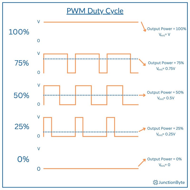
Pulse Width Modulation (PWM) is a technique used to control the average voltage delivered to a load by rapidly switching a signal between HIGH and LOW states. PWM manipulates the Duty Cycle of a periodic digital signal to regulate power distribution.
Duty Cycle is the proportion of the signal in its HIGH (or ON) state relative to one complete cycle (which is the sum of HIGH and LOW — OFF states). The modulation occurs by varying the duty cycle i.e., percentage of the time the signal remains high during each cycle.
A 50% duty cycle means the signal stays HIGH for half the period and LOW for the remaining time. A higher duty cycle increases the average voltage (and thus the power delivery), while a lower duty cycle reduces it. For instance, a motor running at 50% duty cycle operates at half its maximum speed.
PWM effectively converts digital signals into varying power levels i.e., a digital way to produce analog signals.
Motor control is one of the most common applications of PWM. By adjusting the duty cycle, we can regulate the motor speed without affecting torque significantly. Servo Motors need a PWM signal to adjust the position of the shaft.
Another significant use of PWM is LED dimming. Instead of using resistors to limit current, PWM adjusts brightness by controlling the duration of the ON state. A high duty cycle results in brighter illumination, while a low duty cycle produces dim light.
Duty Cycle and Frequency
As I already stated above, Duty Cycle is the percentage of one cycle that the signal remains in the HIGH state. It is one of the key parameters of a PWM signal. We can adjust this percentage to control the output power.
Frequency, which is measured in Hertz (Hz), is a measure of how many times the signal completes a full cycle per second. Higher frequencies create smoother outputs, especially in motor control (reduces noise and vibrations).
Conversely, LEDs work well with lower frequencies, typically between 100 Hz and 1 kHz, to avoid flickering.
HIGH (ON) Time and LOW (OFF) Time
Each PWM cycle consists of two parts: HIGH time and LOW time. HIGH time is the duration the signal remains in the ON state. LOW time, on the other hand, is the duration it stays in the OFF state.
By adjusting these values, we can alter the output power. For example, a PWM signal with 70% duty cycle stays ON or HIGH for 70% of the total period and remains OFF for the remaining 30%.
Mathematical Representation of PWM
We can mathematically represent a PWM using duty cycle, period, and frequency.
The duty cycle (D) is equal to the ratio of HIGH or ON time (TON) to the total period (T = TON + TOFF). It is given by:
D = (TON / T) × 100%
where T = TON + TOFF
The period (T) and frequency (f) relate through the formula: T = 1 / f
How to Generate PWM in an 8051 Microcontroller?
Sadly, the standard 8051 microcontroller does not come with a hardware PWM module. So, how can we generate PWM in 8051?
Similar to the I2C Protocol that we saw in the previous 8051 Microcontroller I2C Guide, we rely on software-driven techniques for PWM generation. To implement PWM through software, we need to toggle the output pins at precise intervals. Timers and interrupts help achieve this.
Software Delays
One of the simplest ways to generate PWM signals is by software delays where we toggle an output pin at fixed intervals. We can adjust the duty cycle by controlling the delay durations for the ON and OFF times.
This method requires no hardware configuration but consumes significant CPU time and resources. Since the processor continuously executes delay loops, this will prevent it from handling other tasks efficiently. There is a good chance of timing inconsistencies due to variations in instruction execution time.
Using Timers
Hardware timers are a reliable way to generate PWM. Even in this method we toggle the output pins at precise intervals. However, the CPU isn’t stuck executing delay loops continuously. Instead, we use the Timers to generate the delays and thereby reduce the CPU overhead.
By configuring a Timer in Mode 1 (16-bit Mode) or Mode 2 (Auto-reload Mode), we can create periodic interrupts to toggle an output pin. To control the duty cycle, we can adjust the timer reload value. When the Timer reaches a set value, an interrupt routine executes to toggle the output pin.
Generating PWM using 8051 Timer
For the first example, I will use Timer 0 of the 8051 Microcontroller in Mode 2 (Auto-reload Mode) to generate a PWM signal. To demonstrate the working, I created a simple ‘LED Fade’ or ‘Breathing LED’ application, where the LED gradually increases and gradually decreases.
First, I will provide the code (with ample comments for you to understand) and then later I will explain the logic behind the code.
#include <reg52.h>

/* Define the PWM Pin */
sbit PWM_PIN = P1^0;  /* You can connect an LED to P1.0 */

#define MAX_DUTY_CYCLE 255  /* 8-bit resolution (0-255) */

/* A Variable for Duty cycle for PWM */
volatile unsigned char duty_cycle = 0;

/* A variable for indicating Fade Direction
 * 1 for increasing duty cycle and 0 for decreasing duty cycle */
volatile unsigned char fade_direction = 1;

/* Function Prototypes */
void initPWM(void);
void updateDutyCycle(void);

/* Function Definitions */

/* Function to Initialize PWM */
void initPWM(void)
{
  /* Set the LED Pin as output */
  PWM_PIN = 0;
  /* Configure Timer 0 in 8-bit Auto-reload Mode (Mode 2) */
  TMOD |= 0x02;  /* Timer 0 in Mode 2 (8-bit Auto-reload) */
  /* Set Reload Value for Timer 0 based on PWM Frequency */
  TH0 = 256 - (11059200 / 12 / 255);
  TL0 = TH0;  /* Initialize Timer 0 */
  /* Enable Timer 0 Interrupts */
  ET0 = 1;
  EA = 1;

  /* Start Timer 0 */
  TR0 = 1;
}

/* Timer 0 Interrupt Service Routine (ISR) */
void timer0_ISR(void) interrupt 1
{
  static unsigned char counter = 0;
  /* Update the PWM Signal based on the current Duty Cycle */
  if (counter < duty_cycle)
  {
    PWM_PIN = 1;  /* PWM ON State */
  }
  else
  {
    PWM_PIN = 0;  /* PWM OFF State */
  }

  /* Increment the counter */
  counter++;

  /* Reset counter when it reaches 255 (one full PWM period) */
  if (counter >= 255)
  {
    counter = 0;
  }
}

/* Function to Update the Duty Cycle for the Fading Effect */
void updateDutyCycle(void)
{
  /* Change the Duty Cycle based on the fade direction */
  if (fade_direction == 1)
  {
    duty_cycle++;  /* Increase the Duty Cycle */
    if (duty_cycle == MAX_DUTY_CYCLE)
    {
      /* Reverse direction when the Max Duty Cycle is reached */
      fade_direction = 0;
    }
  }
  else
  {
    duty_cycle--;  /* Decrease the Duty Cycle */
    if (duty_cycle == 0)
    {
      /* Reverse direction when the min Duty Cycle is reached */
      fade_direction = 1;
    }
  }
}

/* Main Function */
void main(void)
{
  unsigned long i = 0; /* Variable for Delay */
  /* Initialize PWM */
  initPWM();
  /* Main loop */
  while (1)
  {
    /* Update Duty Cycle to create the fading effect */
    updateDutyCycle();
    /* Small delay to control the fading speed */
    for ( i = 0; i < 10; i++);
  }
}
PWM Initialization (initPWM)
void initPWM(void)
{
  /* Set the LED Pin as output */
  PWM_PIN = 0;
  /* Configure Timer 0 in 8-bit Auto-reload Mode (Mode 2) */
  TMOD |= 0x02;  /* Timer 0 in Mode 2 (8-bit Auto-reload) */
  /* Set Reload Value for Timer 0 based on PWM Frequency */
  TH0 = 256 - (11059200 / 12 / 255);
  TL0 = TH0;  /* Initialize Timer 0 */
  /* Enable Timer 0 Interrupts */
  ET0 = 1;
  EA = 1;

  /* Start Timer 0 */
  TR0 = 1;
}- PWM_PIN = 0;
- This sets the LED connected to P1.0 (assuming the LED is connected to this pin) to an initial ‘OFF’ state.
- TMOD |= 0x02;
- We know that the TMOD register configures the Timer Modes. The value ‘0x02’ selects Timer 0 in Mode 2, which is an 8-bit auto-reload mode. This means the timer will count from 0 to 255 (8-bit value) and then automatically reload from the value in the TH0 register to repeat the counting.
- TH0 = 256 – (11059200 / 12 / 255);
- The Timer Overflow Rate determines the PWM Frequency. We calculate the appropriate value for TH0 (which sets the reload value for Timer 0) using the following parameters:
- Crystal frequency: 11.0592 MHz
- The 8051 microcontroller divides the clock by 12 to get the machine cycle frequency, so the effective clock speed for the microcontroller is 11.0592 MHz / 12 = 921,600 Hz.
- The above formula calculates the number of machine cycles required to generate a PWM frequency with a 255 steps period (because we’re using 8-bit PWM, where the counter will go from 0 to 255).
- ET0 = 1; enables the interrupt for Timer 0.
- EA = 1; enables global interrupts in the microcontroller.
- TR0 = 1; starts Timer 0, which will begin counting and generating interrupts at the specified frequency.
Timer Interrupt Service Routine (timer0_ISR)
void timer0_ISR(void) interrupt 1
{
  static unsigned char counter = 0;
  /* Update the PWM Signal based on the current Duty Cycle */
  if (counter < duty_cycle)
  {
    PWM_PIN = 1;  /* PWM ON State */
  }
  else
  {
    PWM_PIN = 0;  /* PWM OFF State */
  }

  /* Increment the counter */
  counter++;

  /* Reset counter when it reaches 255 (one full PWM period) */
  if (counter >= 255)
  {
    counter = 0;
  }
}- The timer0_ISR function is called every time Timer 0 overflows, which happens at the PWM frequency (about 1 kHz, as set by the timer configuration).
- Inside the ISR, we check if the current counter value is less than the duty_cycle. The counter variable counts from 0 to 255, and the duty_cycle is the threshold at which we switch the LED ON or OFF.
- If counter < duty_cycle, the LED is turned ON (PWM_PIN = 1;).
- If counter >= duty_cycle, the LED is turned OFF (PWM_PIN = 0;).
- This generates a PWM signal where the duration of the “ON” state depends on the duty cycle. For example:
- If duty_cycle = 127, the LED will be ON for 127 counts and OFF for the remaining 128 counts, creating a 50% duty cycle.
- If duty_cycle = 255, the LED will stay on throughout the full period, creating a 100% duty cycle.
- The counter is incremented after each interrupt to track the current position in the PWM cycle.
- Once the counter reaches 255, it is reset to 0 to start a new cycle. This effectively defines one complete PWM period (which lasts for 255 timer ticks).
Updating Duty Cycle for Fading (updateDutyCycle)
void updateDutyCycle(void)
{
  /* Change the Duty Cycle based on the fade direction */
  if (fade_direction == 1)
  {
    duty_cycle++;  /* Increase the Duty Cycle */
    if (duty_cycle == MAX_DUTY_CYCLE)
    {
      /* Reverse direction when the Max Duty Cycle is reached */
      fade_direction = 0;
    }
  }
  else
  {
    duty_cycle--;  /* Decrease the Duty Cycle */
    if (duty_cycle == 0)
    {
      /* Reverse direction when the min Duty Cycle is reached */
      fade_direction = 1;
    }
  }
}- This function controls the “fading” of the LED by gradually changing the duty cycle. The fade_direction variable determines whether the duty cycle should increase or decrease.
- Increasing Duty Cycle:
If fade_direction == 1 (fading up), the duty cycle is incremented by 1 (duty_cycle++). When it reaches the maximum value (255), the direction is reversed (fade_direction = 0), so the duty cycle will start decreasing. - Decreasing Duty Cycle:
If fade_direction == 0 (fading down), the duty cycle is decremented by 1 (duty_cycle–). When it reaches the minimum value (0), the direction is reversed (fade_direction = 1), and the duty cycle will start increasing again.
- Increasing Duty Cycle:
- This creates a smooth fading effect where the LED gradually brightens (as the duty cycle increases) and dims (as the duty cycle decreases).
8051 Microcontroller PWM Driver
To make the PWM code more modular and reusable, we can re-write and organize the previous code into a PWM driver with functions for initialization, starting, stopping, and setting the duty cycle.
- PWM_Init: Initializes the PWM hardware. This function includes Timer 0 configuration and setting up necessary Timer registers.
- PWM_Start: Starts the PWM signal by enabling the Timer.
- PWM_Stop: Stops the PWM signal by disabling the Timer.
- PWM_SetDutyCycle: Allows changing the Duty Cycle of the PWM Signal dynamically.
#ifndef AT89S52_PWM_H_
#define AT89S52_PWM_H_

#include <reg52.h>
/* Define a Pin for PWM Output */
sbit PWM_PIN = P1^0;

/* Define a Constant for Maximum Duty Cycle
 * With 8-Bit Resolution, the range will be 0 - 255 */
#define MAX_DUTY_CYCLE 255

/* Declare variables for PWM */
/* Variable for Current Duty Cycle (0 to 255) */
static volatile unsigned char dutyCycle = 0;
/* Flag to check if PWM is running */
static volatile unsigned char pwmRunning = 0;

/* PWM Function Prototypes */
void PWM_Init(void);
void PWM_Start(void);
void PWM_Stop(void);
void PWM_SetDutyCycle(unsigned char percentage);

/* PWM Initialization */
void PWM_Init(void)
{
  /* Set PWM Pin as Output */
  PWM_PIN = 0;

  /* Configure Timer0 in 8-Bit Auto-reload Mode (Mode 2)*/
  TMOD |= 0x02;
  /* Set Reload value for Timer 0 based on desired frequency */
  TH0 = 256 - (11059200 / 12 / 255);
  /* Initialize Timer 0 */
  TL0 = TH0;

  /* Enable Timer 0 Interrupts */
  ET0 = 1; /* Enable Timer 0 Interrupt */
  EA = 1; /* Enable Global Interrupts */
}

/* Start PWM Signal Generation */
void PWM_Start(void)
{
  if (!pwmRunning)
  {
    pwmRunning = 1;  /* Mark PWM as running */
    TR0 = 1;  /* Start Timer 0 */
  }
}

/* Stop PWM Signal Generation */
void PWM_Stop(void)
{
  if (pwmRunning)
  {
    pwmRunning = 0;  /* Mark PWM as stopped */
    TR0 = 0;  /* Stop Timer 0 */
    PWM_PIN = 0;  /* Turn OFF PWM Pin when PWM stops */
  }
}

/* Set PWM Duty Cycle (Percentage: 0-100) */
void PWM_SetDutyCycle(unsigned char percentage)
{
  if (percentage <= 100)
  {
    /* Convert percentage to 0-255 range */
    dutyCycle = (percentage * MAX_DUTY_CYCLE) / 100;
  }
}

/* Timer 0 Interrupt Service Routine (ISR) */
void PWM_ISR(void) interrupt 1
{
  static unsigned char counter = 0;
  /* Update the PWM Signal based on the Duty Cycle */
  if (counter < dutyCycle)
  {
    PWM_PIN = 1;  /* PWM Pin HIGH/ON */
  }
  else
  {
    PWM_PIN = 0;  /* PWM Pin LOW/OFF */
  }

  /* Increment the counter */
  counter++;

  /* Reset counter when it reaches 255 (one full PWM period) */
  if (counter >= 255)
  {
    counter = 0;
  }
}

#endif
The working of this driver is exactly the same as the previous barebones example. So, I won’t into those details.
8051 Microcontroller PWM Driver Demo
The following code is a simple example demonstrating the previous PWM Driver. Here, I am just setting the PWM Duty Cycle by calling the PWM_SetDutyCycle() function. You can use this driver to experiment with different PWM Duty Cycles.
#include <reg52.h>
#include "at89s52_pwm.h"

#define MAX_DUTY_CYCLE_PERCENTAGE 100
void main(void)
{
  /* Variable for Delay */
  unsigned long j = 0;
  /* Initialize PWM Driver */
  PWM_Init();
  /* Start PWM Signal Generation */
  PWM_Start();

  while (1)
  {
    PWM_SetDutyCycle(25);
    for (j = 0; j < 10000; j++); /* A loop Delay */
    PWM_SetDutyCycle(50);
    for (j = 0; j < 10000; j++); /* A loop Delay */
    PWM_SetDutyCycle(75);
    for (j = 0; j < 10000; j++); /* A loop Delay */
    PWM_SetDutyCycle(100);
    for (j = 0; j < 10000; j++); /* A loop Delay */
  }
}