Using Arduino IDE with STM32G4 MCUs is okay for quick prototyping. However, if you are developing a custom product and need to configure each and every pin of the microcontroller in your program, then you need a more “professional” development platform. ARM’s Keil MDK (Microcontroller Development Kit) is one of the popular IDEs in the embedded community. The free version is code-limited and is for non-commercial purposes. A great alternative, especially if you are working exclusively with STM32 MCUs, is the STM32CubeIDE. This is the Getting Started with STM32CubeIDE and STM32G4 MCUs guide.
In this guide, we will learn everything about the STM32CubeIDE such as its installation, creating a project, configuring the STM32G4 MCU from scratch, writing a simple application, and uploading the code.
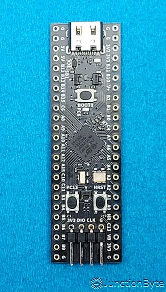
In the previous guide, I made a very-detailed Introduction to STM32G4 Series with Arduino IDE and a WeAct Studio STM32G431 Core Board. I discussed a lot of basics about STM32G4 MCU in that guide as well as how to configure Arduino IDE to work with STM32G431 Core Board. Do check it out before proceeding further with this guide.
A Brief Note on STM32CubeIDE
STM32CubeIDE, as the name suggests, is an integrated development environment from STMicroelectronics specifically designed for STM32 Microcontrollers. It is based on the popular Eclipse IDE. You can develop applications in C and C++ programming languages.
While the Eclipse framework acts as the backend tool, ST did a lot of customization to the final software. Using STM32CubeIDE, you can configure the pins and peripherals of an MCU, integrate necessary libraries, generate basic start-up code, compile the code (ARM GCC), upload the code, and even debug the hardware (GDB).
There are a lot more features and functionalities that the STM32CubeIDE offers and we will get to know them in the later part of this guide (or in future guides).
Install STM32CubeIDE
The first step, when it comes to working with the STM32CubeIDE, is to install it on your computer. Here’s a link to the official download page of STM32CubeIDE. You need to have an account with ST in order to download any software development tools from ST.
After logging in and downloading the tool, extract the zip file and run the executable. The whole installation process is very straightforward and you can leave all the options to their default values.
Launch STM32CubeIDE
Once the installation completes, we are now ready to use the tool. Launch the STM32CubeIDE tool (either from the desktop shortcut or by searching from the Start menu).
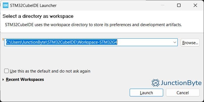
The first thing the IDE asks you is to select a directory that acts as the Workspace. A Workspace in STM32CubeIDE is nothing but a folder that contains many projects. You can create as many workspaces as you want but only one will be active at any time. For instance, you can have one workspace that contains all the projects for STM32G431 Core Board and another workspace that contains the projects for the STM32 Blue Pill.
Coming back to the IDE, you can either leave the default location for the workspace or choose a particular folder where you can keep all your projects.
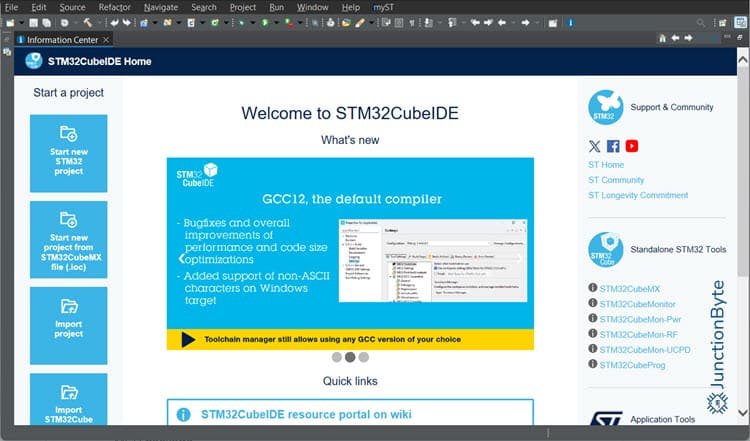
After this, the IDE will launch with an ‘Information Center’ tab. Before we create a project, there is one important step we need to perform.
Install Software Packages
We know that ‘STM32’ is a huge collection of MCUs that are categorized as follows:
- High performance – STM32F7, STM32H7, STM32F4, etc.
- Mainstream – STM32F1, STM32G0, STM32G4, etc.
- Ultra-low-power – STM32U0, STM32L0, STM32FL4, etc.
- Wireless – STM32WL, STM32WB, STM32WBA, etc.
What ST did with these different series is it created software packages for the individual MCU platforms that contains all the low-level files specific to that series. These are known as STM32Cube MCU Package. A package usually consists of HAL (Hardware Abstraction Layer) APIs, LL (Low-layer) APIs, ARM Cortex-M CMSIS files, BSP (Board Support Package) files, additional utilities and drivers (USB, FreeRTOS, etc.), and a few example projects.
If you take the STM32 Blue Pill for example, it has the STM32F103C8T6 MCU on it. So, we will need the ‘STM32CubeF1’ MCU Package. Similarly, since we are using the STM32G431 Core Board in this guide, we need the STM32CubeG4 MCU package.
It doesn’t come with the STM32CubeIDE (in fact, none of the STM32Cube Packages will come pre-installed) and you have to install the necessary packages yourself.
But before that, you need to login with your ST account. In the STM32CubeIDE, go to myST->Login and enter your credentials.
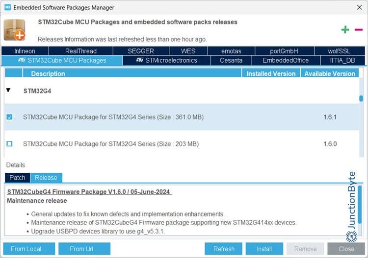
After successful login, go to Help->Manage Embedded Software Packages option. A new window with title ‘Embedded Software Packages Manager’ will popup.
Select the ‘STM32Cube MCU Packages’ tab in the top, scroll down and find the ‘STM32G4’ series, expand it, select the latest package, and click on install.
The IDE will automatically download and install the software package. If you are working on a different MCU say, for instance, the STM32F429ZIT6, which is on the STM32F429I-DISC1 Discovery Development Board, then you need to download the software package for ‘STM32F4’ series using the same procedure.
Create a New STM32 Project in STM32CubeIDE
We are now ready to create our first project in the STM32CubeID. If you are still on the ‘Information Center’ tab, you can see a ‘Start a Project’ section on the top left corner. To create a new project, click on ‘Start new STM32 project’ option. Alternatively, you can use File -> New -> STM32 Project option as well.
Now, the IDE will start a ‘Target Selector’ window, where we have to select the microcontroller we are working on. In the text field next to ‘Commercial Part Number,’ type ‘STM32G431CBU6’ as this is the MCU on the WeAct STudio STM32G431 Core Board.
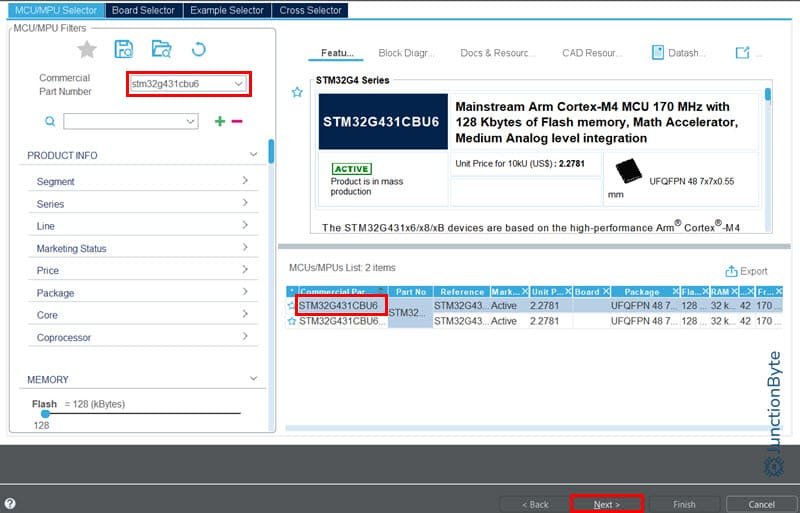
If you are using a standard development board (Discovery or Nucleo), then you can directly select this board and the Tool will pre-configure some stuff as per the board specifications.
On the right side, you can see the tool filtered out only two MCUs. When you click on the part ‘STM32G431CBU6,’ the tool will display features of this particular MCU. You can go through it, if you want to. Click on ‘Next.’ Then, give a proper name to this project. You can leave the rest of the options at their default values.
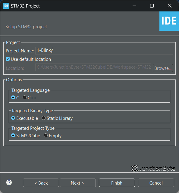
Once again click on ‘Next’ and then on the ‘Finish’ button. As soon as you click on the ‘Finish’ button, the IDE will activate the ‘Device Configuration Tool’ and ask you whether to switch to that perspective. Click on ‘Yes.’
Now, we need to configure the MCU (STM32G431CBU6, in this case) as per the schematic of the development board.
STM32CubeIDE Device Configuration Tool
Before proceeding further, you will need access to the schematic of the development board so that we can see the components and connections they made with respect to the microcontroller. Here’s a link to the schematic of the WeAct Studio STM32G431 Core Board.
That said, the first thing that grabs your attention in the Device Configuration Tool is the ‘Pinout View’ of the MCU.
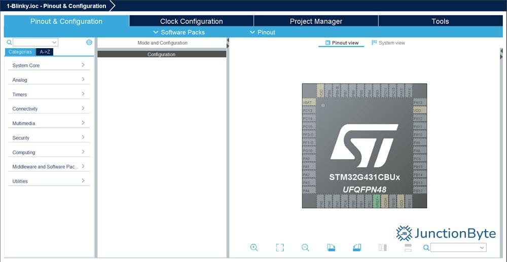
We will configure some of the important pins and peripherals of the MCU and explore the tool in the process. Let us begin with the clock circuit.
Clock Tree Configuration
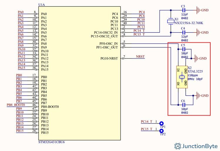
The STM32G431CBU6 MCU has a built-in high-speed clock (an RC Oscillator). However, since our development board comes with a proper high-speed external clock in the form of a crystal oscillator, we are going to use that. If you look at the schematic, the 8MHz Crystal is connected across the pins 5 (PF0-OSC_IN) and 6 (PF1-OSC_OUT).
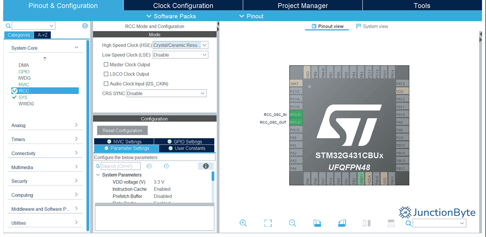
In the Device Configuration Tool, expand the ‘System Core’ and select the ‘RCC’ peripheral (which is the Reset and Clock Controller). The ‘Mode’ configuration panel on the right will become active with settings related to this particular peripheral (RCC in this case).
Set the HSE (High-Speed External Clock) to Crystal/Ceramic Resonator. As soon as you do this, the two oscillator pins on the MCU (PF0-OSC_IN and PF1-OSC_OUT) will become active and the tool assigns labels to those pins (RCC_OSC_IN and RCC_OSC_OUT).
We can further customize the clock by going to the ‘Clock Configuration’ tab on the top. This will open the complete clock tree of this microcontroller. Even though we enabled the external clock source, the tool still uses the HSI (High-speed Internal) as the main clock source. If we don’t configure, the code generated by the tool will be for HSI and not HSE.
First, set the HCLK to 170MHz and hit enter. The tool will automatically adjust the rest of the parameters for you. Now change the PLL Source to HSE and once again set the HCLK to 170MHz. As you can see, all the peripheral clocks are set at 170MHz.
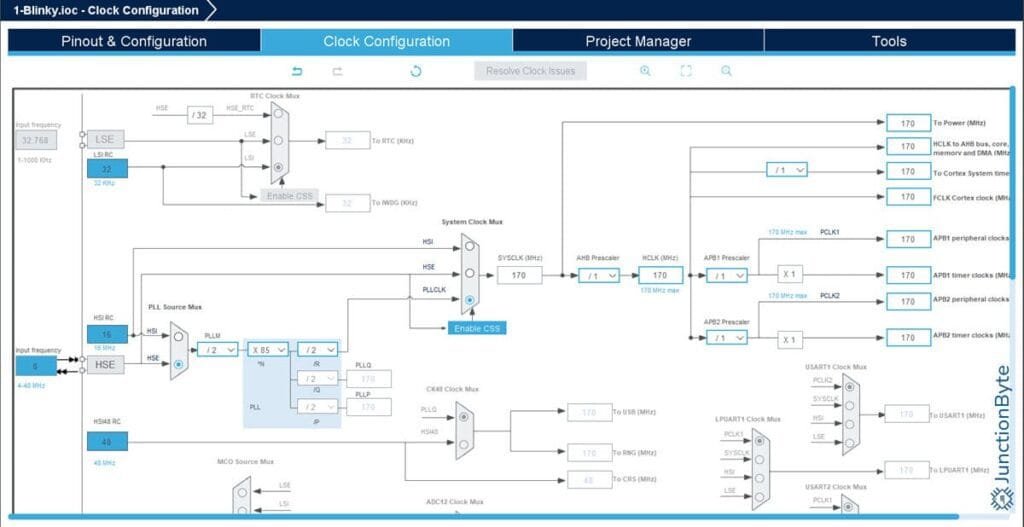
You can play with the clock tree a little bit but make sure that HSE of 8MHz is the main input clock.
GPIO Configuration
Let us now configure the GPIO. The WeAct Studio STM32G431 Core Board has a user LED at PC6 and a user button at PC13. For this guide, we will use both these components. But first, we need to configure the GPIO peripheral of the MCU.
Go back to the ‘Pinout & Configuration’ tab and in the ‘Pinout view’ find the ‘PC6’ pin. You can use the search bar at the bottom. Click on the ‘PC6’ pin and set it as ‘GPIO_Output’ (since it is connected to the LED).
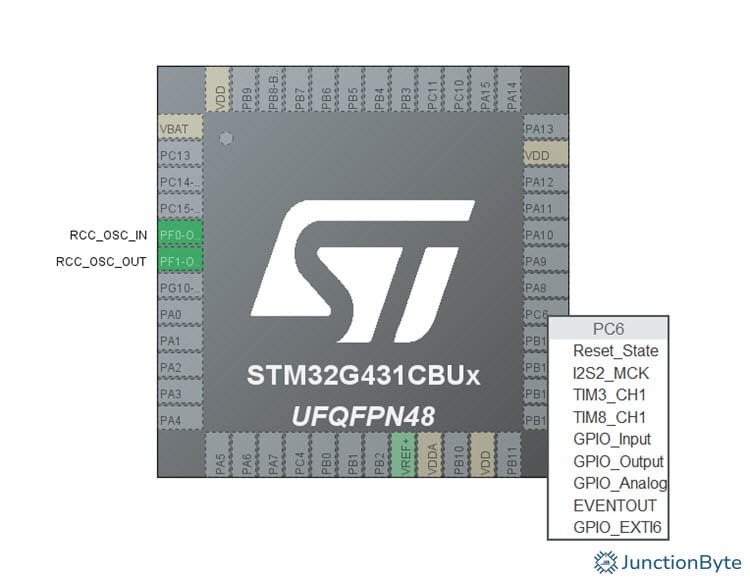
Right-click on the same pin (PC6) and select ‘Enter User Label’ option. Here, you can give a meaningful name to the pin (for example, userLED) and the tool will use this name in the code.
Coming to the push button, if you look at the schematic, the pin PC13 is connected to one end of the button (through a current limiting resistor) and the other end of the button is connected to 3.3V.
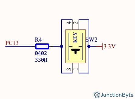
We now have to configure the pin PC13 as input. You already know how to do it. Look for ‘PC13’ in the Pinout view, click on the pin, and select ‘GPIO_Input’ from the list. I gave this pin a label ‘BUTTON’ but you can give whatever you want.
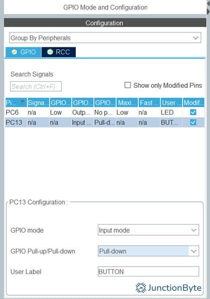
There is one more thing we need to configure with this pin. Since the pin is floating when we don’t push the button, it is not the best practice to leave it like that. We can use the internal pull-down (or pull-up depending on the circuit) provided by the MCU. To activate this, expand ‘System Core’ on the left menu, select GPIO, click on PC13, and set ‘GPIO Pull-up/Pull-down’ to ‘Pull-down’ in the configuration tab.
Debug (SWD) Configuration
The last important device configuration that we need to perform in the ‘Device Configuration Tool’ is to enable the debug pins. I will be using ST-LINK to program the STM32431 Core Board. So, we have to configure the ‘SWD’ pins of the MCU. If you remember the board layout, the bottom short edge of the WeAct Studio STM32431 Core Board has the pins for SWD interface.
The simplest way to enable SWD is as follows: expand ‘System Core’ from the left, click on SYS, and in the ‘Debug’ option in the Mode Configuration, select ‘Serial Wire.’ As soon as you do this, the two pins on the MCU (PA13 and PA14) will be set as SWDIO and SWCLK respectively.
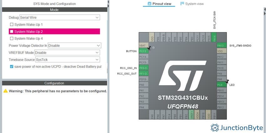
While we are here, you can see the ‘Timebase’ option below the ‘Debug’ mode. Set it to ‘SysTick.’ We will be using this to blink the LED without using any ‘delay’ functions.
Code Generation
When you save the ‘Device Configuration Tool,’ the IDE will ask you if you want it to generate the code. Click ‘Yes’ and it will immediately ask you to switch perspective (from device configuration to C/C++). Once again, click on the ‘Yes’ option and it will open the ‘main.c’ file.
You have to explore this perspective a bit as there are a lot of things going on. First of all, on the left side, you can see all the source files used in the project. This includes the code generated by the IDE, library files from ST (remember we downloaded the software packages), and many others.
Write Your First Program in STM32CubeIDE for STM32G4
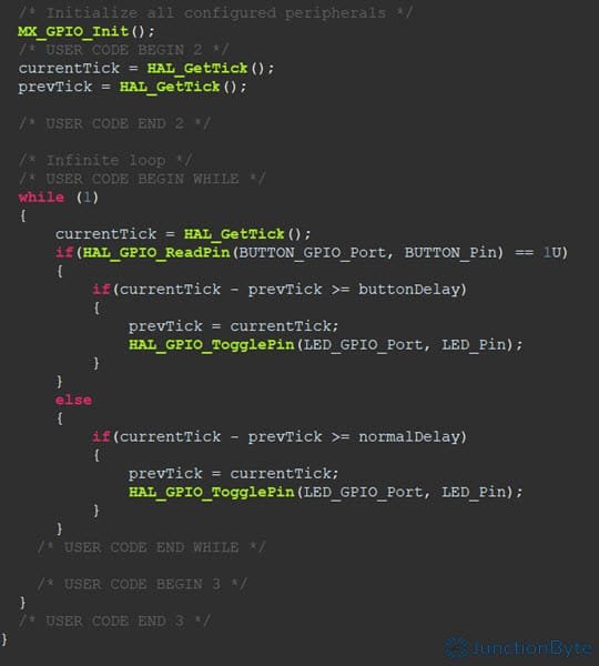
For this getting started with STM32CubeIDE and STM32G4 Series guide, we will create a simple application using the on-board LED and the user button. The final application should look something like this: the LED blinks normally (ON for 1s, OFF for 1s) but when you press and hold the button, it blinks rapidly (ON for 200ms, OFF for 200ms).
I will first show the full code (the main.c file) here for your reference.
#include "main.h"

uint32_t currentTick, prevTick;
uint32_t normalDelay = 1000;
uint32_t buttonDelay = 200;

void SystemClock_Config(void);
static void MX_GPIO_Init(void);

int main(void)
{
  HAL_Init();
  SystemClock_Config();
  MX_GPIO_Init();

  currentTick = HAL_GetTick();
  prevTick = HAL_GetTick();
  while (1)
  {
      currentTick = HAL_GetTick();
      if(HAL_GPIO_ReadPin(BUTTON_GPIO_Port, BUTTON_Pin) == 1U)
      {
          if(currentTick - prevTick >= buttonDelay)
          {
              prevTick = currentTick;
              HAL_GPIO_TogglePin(LED_GPIO_Port, LED_Pin);
          }
      }
      else
      {
          if(currentTick - prevTick >= normalDelay)
          {
          	  prevTick = currentTick;
          	  HAL_GPIO_TogglePin(LED_GPIO_Port, LED_Pin);
          }
      }
  }
}

void SystemClock_Config(void)
{
  RCC_OscInitTypeDef RCC_OscInitStruct = {0};
  RCC_ClkInitTypeDef RCC_ClkInitStruct = {0};

  HAL_PWREx_ControlVoltageScaling(PWR_REGULATOR_VOLTAGE_SCALE1_BOOST);

  RCC_OscInitStruct.OscillatorType = RCC_OSCILLATORTYPE_HSE;
  RCC_OscInitStruct.HSEState = RCC_HSE_ON;
  RCC_OscInitStruct.PLL.PLLState = RCC_PLL_ON;
  RCC_OscInitStruct.PLL.PLLSource = RCC_PLLSOURCE_HSE;
  RCC_OscInitStruct.PLL.PLLM = RCC_PLLM_DIV4;
  RCC_OscInitStruct.PLL.PLLN = 85;
  RCC_OscInitStruct.PLL.PLLP = RCC_PLLP_DIV2;
  RCC_OscInitStruct.PLL.PLLQ = RCC_PLLQ_DIV2;
  RCC_OscInitStruct.PLL.PLLR = RCC_PLLR_DIV2;
  if (HAL_RCC_OscConfig(&RCC_OscInitStruct) != HAL_OK)
  {
    Error_Handler();
  }

  RCC_ClkInitStruct.ClockType = RCC_CLOCKTYPE_HCLK|RCC_CLOCKTYPE_SYSCLK
                              |RCC_CLOCKTYPE_PCLK1|RCC_CLOCKTYPE_PCLK2;
  RCC_ClkInitStruct.SYSCLKSource = RCC_SYSCLKSOURCE_PLLCLK;
  RCC_ClkInitStruct.AHBCLKDivider = RCC_SYSCLK_DIV1;
  RCC_ClkInitStruct.APB1CLKDivider = RCC_HCLK_DIV1;
  RCC_ClkInitStruct.APB2CLKDivider = RCC_HCLK_DIV1;

  if (HAL_RCC_ClockConfig(&RCC_ClkInitStruct, FLASH_LATENCY_4) != HAL_OK)
  {
    Error_Handler();
  }
}

static void MX_GPIO_Init(void)
{
  GPIO_InitTypeDef GPIO_InitStruct = {0};
  __HAL_RCC_GPIOC_CLK_ENABLE();
  __HAL_RCC_GPIOF_CLK_ENABLE();
  __HAL_RCC_GPIOA_CLK_ENABLE();

  HAL_GPIO_WritePin(LED_GPIO_Port, LED_Pin, GPIO_PIN_RESET);

  GPIO_InitStruct.Pin = BUTTON_Pin;
  GPIO_InitStruct.Mode = GPIO_MODE_INPUT;
  GPIO_InitStruct.Pull = GPIO_PULLDOWN;
  HAL_GPIO_Init(BUTTON_GPIO_Port, &GPIO_InitStruct);

  GPIO_InitStruct.Pin = LED_Pin;
  GPIO_InitStruct.Mode = GPIO_MODE_OUTPUT_PP;
  GPIO_InitStruct.Pull = GPIO_NOPULL;
  GPIO_InitStruct.Speed = GPIO_SPEED_FREQ_LOW;
  HAL_GPIO_Init(LED_GPIO_Port, &GPIO_InitStruct);

}

void Error_Handler(void)
{
  __disable_irq();
  while (1)
  {
  }
}

#ifdef  USE_FULL_ASSERT
void assert_failed(uint8_t *file, uint32_t line)
{
}
#endif
I’ve removed the ‘comments’ part of the code that the IDE generated to post the code here. However, the benefit of this comment section is that if you write your code within the designated areas as shown below, the IDE will keep that code even when you make changes in the Device Configurator Tool.
Upload the Code using ST-LINK
If you have the ST-LINK Programmer and Debugger, it is time to connect it to the STM32G431 Core Board. Do not connect any USB-C Cable when you are using ST-LINK as the ST-LINK hardware will provide the necessary power to the board. The ST-LINK connection is very simple.
| STM32G431 Core Board | ST-LINK |
| GND | GND |
| SWCLK | SWCLK |
| SWDIO | SWDIO |
| 3.3V | 3.3V |
After making the connection, you can click the ‘Run’ option (a white play button in green circle) in the toolbar. A ‘Edit launch configuration properties’ window will pop-up. You can leave everything at the default and click OK.
The IDE will now invoke the ST-LINK GDB server and write the binary to the flash memory of the MCU. It will automatically reset and you can see the code running.
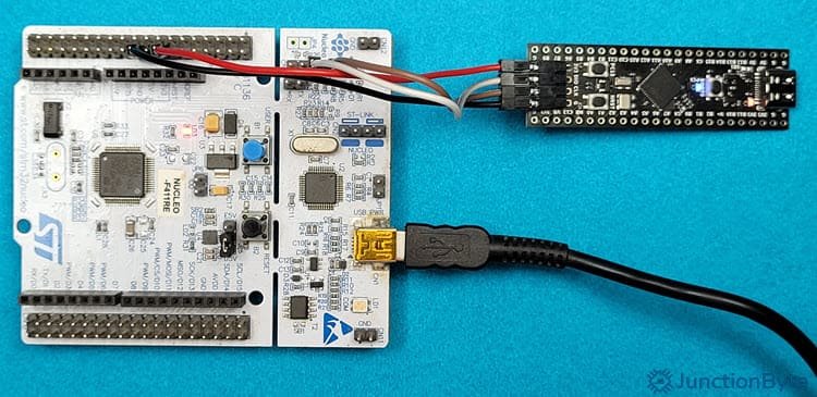
NOTE: I don’t have a dedicated ST-LINK Programmer Module. But I do have a bunch of Discovery and NUCLEO boards from ST. The benefit of these boards is that apart from programming and debugging the on-board MCU, you can use the ST-LINK on them to program external microcontrollers as well. I won’t go into the details but suffice to say that I made essentially the same connections that I mentioned above.
What If You Don’t Have ST-LINK?
I strongly suggest you purchase a cheap ST-LINK Module (where I am from, it is about $1.75). It helps debug your application at a hardware level. However, if you don’t have an ST-Link Programmer Module and want to just upload the code, you can use the USB-DFU upload method that we used in the Arduino tutorial.
First, place the STM32G431 Core Board in ISP Mode. How to do that? With USB-Cable already plugged-in to the computer, press and hold both the RESET and the BOOT0 buttons. First release the RESET button and after a second, release the BOOT0 button. I already discussed in detail about all this in the previous STM32G4 Arduino tutorial.
Now, navigate to ‘C:\Program Files\STMicroelectronics\STM32Cube\STM32CubeProgrammer\bin’ and launch the ‘STM32CubeProgrammer.exe’ file (if you have a desktop shortcut, you can use that).
In the top right corner, select ‘USB’ from the list and refresh the port number. The application will automatically recognize the USB DFU and display the port number. When you click on connect, the software will read data from the memory and display it on the screen.
But we aren’t interested in that. Click on the ‘☰’ icon in the top left and select ‘Erasing & programming’ option. In the File path, you need to give the location of the binary file (it can be .bin, .HEX, or .elf). Now, where do we find the binary files?
If you open the project folder (in my case, it is C:\Users\JunctionByte\STM32CubeIDE\Workspace-STM32G4\1-Blinky), you will see a ‘Debug’ folder. Open it and you can see a .elk file. This is the file we need to give in the STM32CubeProgrammer.
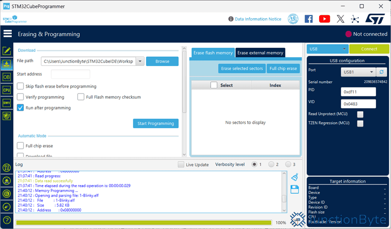
Click the ‘Browse’ button next to the File path option and navigate to this location and select the .elk file. After that, click on the ‘Start Programming’ button and the software will do its magic.
Conclusion
This was an introductory guide on STM32Cube IDE and STM32G4 MCU. In this guide, we saw the basics of STM32CubeIDE (software installation, package installation, project creation, device configuration, code generation, and programming the MCU using ST-LINK and USB DFU).
As this was just a ‘Getting Started with STM32CubeIDE and STM32G4’ guide, I haven’t discussed some of the advanced topics. If you want me to make a dedicated guide on a particular topic, do let me know in the comments section. In the next guide, I will show you how to use the WeAct Studio STM32G431 Core Board with PlatformIO.