If you want to control high power devices such as DC Motors and RGB LEDs using microcontrollers, then you can use transistors (both BJTs and MOSFETS, depending on the requirement) to drive them. Here all the components i.e., the microcontroller, transistor, DC Motor, LED operate over DC voltage (even if they are at different levels). However, if you want to control a device (or an appliance) that works over mains AC voltage, then things can get a little bit tricky. This is where Relays come to the rescue. Relays are a type of switches that help microcontrollers in controlling high-voltage or high-current devices.
Microcontrollers like the 8051 operate at low voltage and current levels. This makes them unsuitable for directly driving heavy loads such as motors, heaters, or industrial machinery. Relays bridge this gap by taking low-power signals from the microcontroller to control high-power circuits. For example, a 5V signal from the 8051 can turn on a 230V AC bulb using a relay.
In this guide, I will cover everything needed to control a relay using an 8051 microcontroller. I will start with some basics such as introduction to relays, their working principle, and different types. Then I will show you how to connect both the standalone relay and relay module to the 8051 microcontroller. Finally, I will provide step-by-step instructions to write and test programs to control the relay.
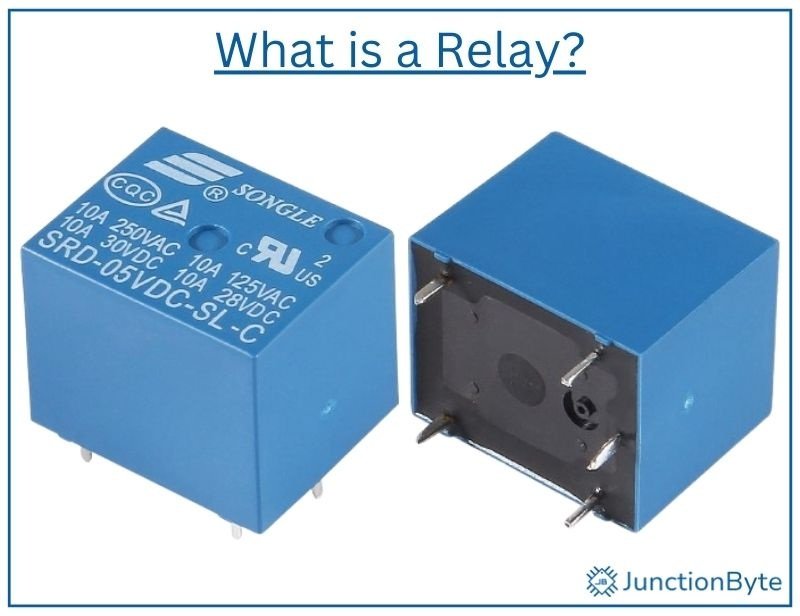
What is a Relay?
A relay is an electromechanical switch that allows a low-power circuit to control a high-power device. A microcontroller, a sensor, or another circuit can activate a relay to turn devices on or off. Unlike mechanical switches, relays use an electromagnet to open or close their contacts.
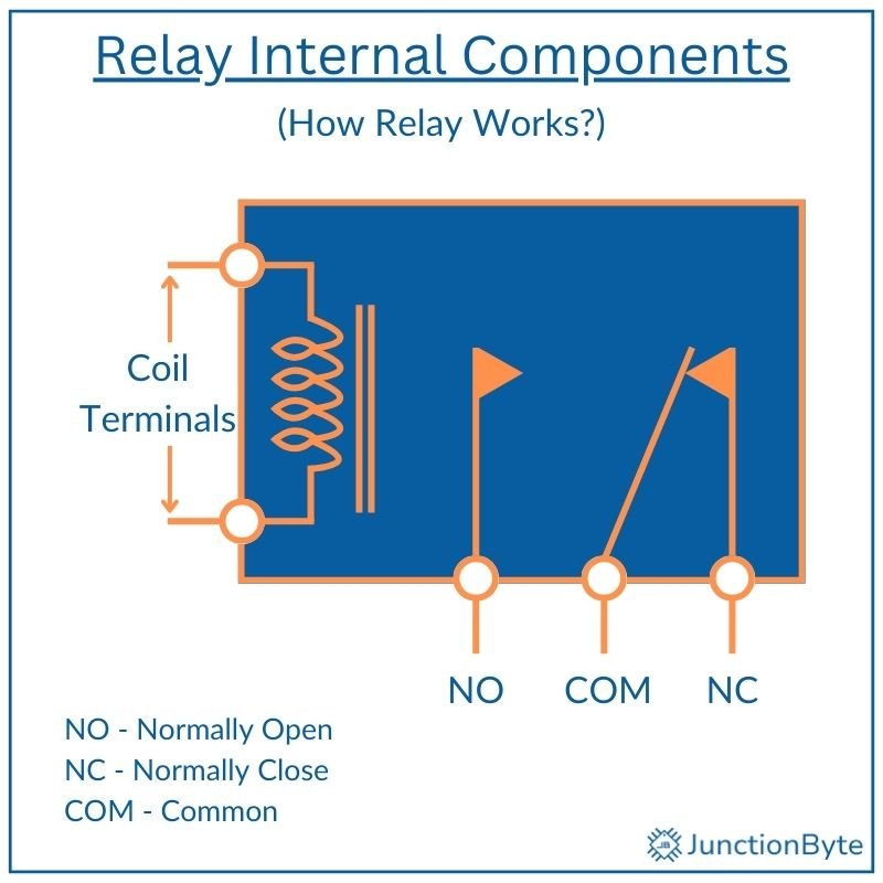
Every relay consists of three main parts: the coil, contacts, and armature.
The coil is a wire winding that generates a magnetic field when current flows through it. The strength of this field depends on the coil’s voltage rating and number of turns.
Next, the contacts form the switching mechanism inside the relay i.e., they determine whether the circuit remains open or closed. The contacts include Normally Open (NO), Normally Closed (NC), and Common (COM) terminals. When the coil is not energized, the COM terminal connects to NC, and when energized, it switches to NO.
The armature is a movable metal part linked to the contacts. When the coil energizes, the magnetic field attracts the armature, changing the contact positions. A spring returns the armature to its original state when the coil deactivates.
How Does a Relay Work?
Relays operate on the principle of electromagnetism. When an electrical current flows through the coil, it creates a magnetic field that attracts the armature. This movement toggles the contacts, either connecting or disconnecting the load circuit.
Types of Relays
There are two types of relays: Electromechanical and Solid State.
Electromechanical relays use a physical movement of armature to switch contacts. These relays handle both AC and DC loads and operate with high reliability in applications that require high current handling.
These relays produce an audible clicking sound when switching. The mechanical movement introduces slight delays and limits the relay’s switching speed. Over time, physical wear can reduce reliability, especially in high-frequency switching applications.
Solid State Relays do not have any moving parts. They rely on semiconductor components like transistors and optocouplers to switch electrical circuits.
Relay Specifications
All relays have three important specifications: Coil voltage, Contact Current Rating, and AC/DC Compatibility.
The coil voltage, typically 5V or 12V, is the voltage necessary to energize the relay’s coil. For example, a 5V relay will switch from NC to NO when there is 5V across the coil.
The contact current rating is the maximum current the relay can handle. A common rating is 10A, which is sufficient to control devices like lights, fans, or small motors. Higher ratings, such as 30A, suit industrial applications with heavier loads.
Additionally, relays also specify whether they support AC, DC, or both. A relay rated for AC can control household appliances, while a DC-rated relay works with batteries or low-voltage systems.
What are Relay Modules?
Controlling a Standalone Relay
Microcontrollers like the 8051 cannot directly power relays due to their high current requirements. That is why we often use a transistor to control the relay coil. A transistor acts as a switch that uses a small current from the 8051 to control a larger current through the relay coil. Common choices for transistors include the BC547 (for low-power relays) and the TIP120 (for high-power applications).
When the relay coil turns off, it generates a high-voltage spike that can damage electronic components (the transistor or microcontroller).
A flyback diode, placed across the coil, safeguards the circuit from back electromotive force (EMF). The diode provides a path for this spike to dissipate harmlessly. The 1N4007 and 1N4148 diodes work well for this purpose.
Relay Module
Relay modules simplify the process of using relays in projects. Unlike standalone relays, these modules come with all the necessary components like driver circuit (consisting of transistor and protection diode) and sometimes isolators (optocoupler) on a single board. This way, we can easily connect a relay to the microcontroller without designing additional circuits.
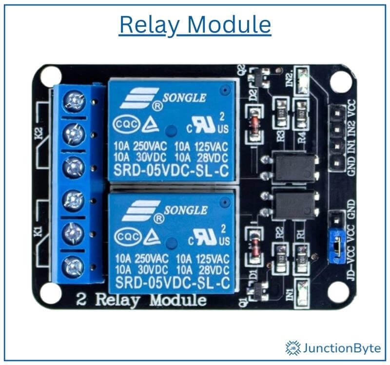
Relay modules are available in various configurations, including 1-channel, 2-channel, and multi-channel versions. A 1-channel relay module, as the name suggests, consists of just one relay that controls a single device. Multi-channel modules can handle multiple devices simultaneously. Many modules also include LED indicators to show the relay’s status.
Most relay modules include three main pins: VCC (power), GND (ground), and IN (control signal). The VCC pin powers the relay coil, while the IN pin receives the control signal from a microcontroller (and turns the transistor ON/OFF). In case of multiple-channel relays, each relay has individual control pins.
Take a note of the triggering mode of the relay module, which is either an active-LOW or active-HIGH. In active-LOW mode, the relay activates when the input signal from the microcontroller is LOW, while active-high mode requires a HIGH signal.
Connecting a Relay to the 8051 Microcontroller
Option 1: Connecting a Standalone Relay
Components Required
- 8051 Microcontroller Development Board
- Relay
- Transistor (BC547 or something similar)
- Resistors (1KΩ, 10KΩ)
- Diode (1N4007)
- Connecting Wires
- Power Supply (for relay)
Circuit Diagram to Control a Relay using an 8051 Microcontroller
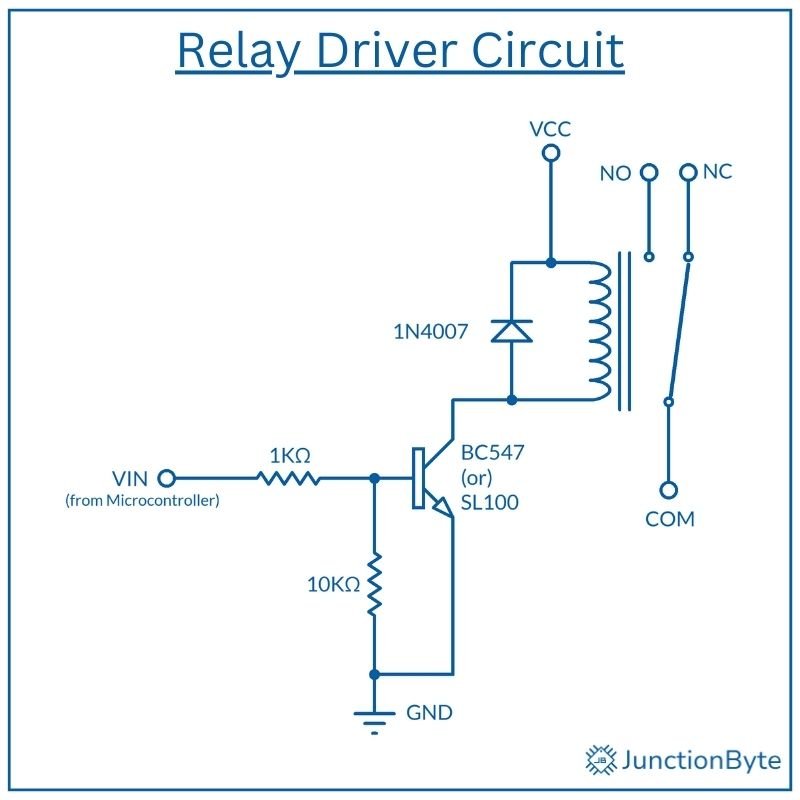
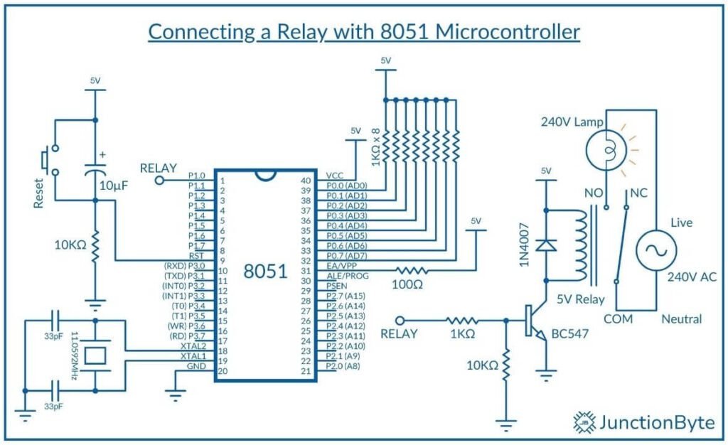
The following image shows the circuit diagram for connecting a standalone relay with an 8051 Microcontroller.
Connections Explained
Here are the steps for connecting a raw standalone relay to the 8051 microcontroller.
First, connect a GPIO pin (P1.0, for example) of the 8051 to a current-limiting resistor (1KΩ). Link the resistor to the base of the transistor (BC547). Connect the transistor’s emitter to ground, collector to one end of the relay coil, and attach the other end of the coil to the power supply (as per relay’s coil voltage).
Pull the base of the transistor to ground using a larger resistor (10KΩ). Finally, place a flyback diode (1N4007) across the relay coil to complete the circuit.
To complete the connection, you can use a standard 240V AC light bulb as a load. Place the light bulb in a bulb holder. Connect one terminal of the bulb holder to the relay module’s NO terminal. The other terminal connects directly to the AC live wire. Finally, connect the relay module’s COM terminal to the AC neutral wire.
WARNING: Handling AC mains voltage without proper precautions can cause electric shocks, burns, or fires. Household outlets typically supply 110V or 240V AC, which can be fatal.
Option 2: Using a Relay Module
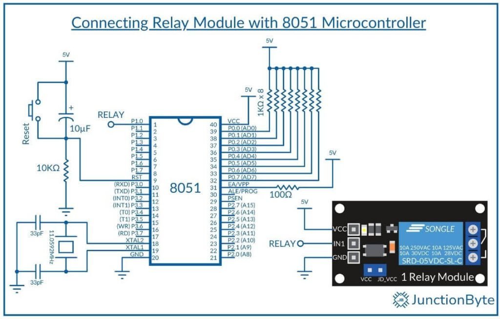
If you have a relay module (which I recommend by the way), connect a GPIO pin of the 8051 to the input pin of the relay module (IN1 or IN2). Connect the module’s VCC and GND pins to an external power supply, typically 5V or 12V, depending on the module’s specifications.
With this setup, you don’t have to worry about additional components like transistors and diodes. The relay module integrates these elements on-board to reduce wiring complexity. The microcontroller’s GPIO pin directly controls the relay module.
Circuit Diagram
Connecting the relay module with 8051 Microcontroller is far simple as you can see from the following circuit diagram.
Program to Control a Relay using an 8051 Microcontroller
Here’s the complete program for relay control using the 8051 microcontroller:
/* Include the main header for register definitions */
#include <reg52.h>
/* Define relay control pin (P1.0) */
sbit relay = P1^0;

/* Delay Function Prototype */
void delay(unsigned int time);

/* Main Function */
void main()
{
  while(1)
  {
    relay = 1;  /* Turn relay ON */
    delay(1000); /* Wait for 1000 ms */
    relay = 0;  /* Turn relay OFF */
    delay(1000); /* Wait for 1000 ms */
  }
}

/* Delay Function*/
void delay(unsigned int time)
{
  unsigned int i, j;
  for(i = 0; i < time; i++)
  {
    for(j = 0; j < 1275; j++);
  }
}
Working of the Project
Before the main logic, we have to include the header file to access the microcontroller-specific functions. The “reg52.h” header file defines special function registers (SFRs) like P1, P2, etc.
Next, the program starts by defining the relay control pin using the ‘sbit’ keyword.
sbit relay = P1^0;
Inside the main() function, the program enters an infinite loop (while (1)). The relay turns ON by setting ‘relay = 1;’, followed by a delay of 1,000 milliseconds. Next, ‘relay = 0;’ turns the relay OFF, and another delay of 1,000 milliseconds maintains the OFF state. This cycle repeats continuously, toggling the relay every second.
void main()
{
  while(1)
  {
    relay = 1;  /* Turn relay ON */
    delay(1000); /* Wait for 1000 ms */
    relay = 0;  /* Turn relay OFF */
    delay(1000); /* Wait for 1000 ms */
  }
}
Use a Button to Control Relay
The previous example code is just for demonstration. However, a more realistic implementation is to let the user control the relay as they wish. For this purpose, we can make use of a simple push button. When the user pushes the button, the 8051 Microcontroller will detect this and toggles the state of the relay (make it ON if it OFF and vice versa).
Code for Relay Control with Button
In the following code, I’m using a push button (connected to P3.2) to control a relay (connected to P1.0). The code takes care of button debouncing as well.
Note that the relay module I have is Active LOW i.e., the relay turn ON (engage) when the Input Signal (Control Signal) from the microcontroller on the IN1 pin is LOW. The relay will turn OFF (disengage) if the IN1 signal is HIGH.
/*Include the header file for the 8051 microcontroller*/
#include <REG52.H>

/*Declare a variable of type 'sbit' for the Port Pin connected to the Push Button*/
sbit BUTTON = P3^2;

/*Declare a variable of type 'sbit' for the Port Pin connected to the Relay*/
sbit RELAY = P1^0;

/*Function prototype for Delay*/
void delay_ms(unsigned int ms); /*Delay Function Declaration*/

/*Main Function*/
void main()
{
  /*Turn OFF Relay on Boot - Active LOW*/
    RELAY = 1;
    /* Make Button Pin Input */
    BUTTON = 1;
  /*Main loop*/
  while(1)
  {
    /*Check if the Push Button is pressed*/
    if (BUTTON == 0)
    {
      /*Since it is an Active-LOW Push Button (pressed = 0)*/
      delay_ms(20);  /*Call the delay function to debounce the switch*/
      /*Recheck the push button state after debounce delay*/
      if (BUTTON == 0)
      {
        /*If button is still pressed after delay*/
        /*Toggle State of the Relay connected to Pin P1.0*/
        RELAY = ~RELAY; /*Relay is Active LOW. 0=ON, 1=OFF*/
      }
    }
  }
}

/*Delay function to generate a time delay in milliseconds*/
void delay_ms(unsigned int ms)
{
  unsigned int i, j;
  for(i = 0; i < ms; i++)
  {
    for(j = 0; j < 1275; j++)
    {
      /*No operation */
      /*Delay of approximately 1 ms*/
    }
  }
}
Conclusion
A relay acts as an electrically operated switch that controls high-power devices using low-power signals. In this project, we learned the basics of relays, including their components and working principle. Then we saw how to connect and control a relay using an 8051 microcontroller.
Now that you understand the fundamentals, you can apply this knowledge to more advanced projects. For example, you can build a smart home system to control lights, fans, and appliances by integrating sensors, wireless communication, or smartphone control.
With sensors like temperature or motion detectors, you can automate these devices based on environmental conditions. You can also add Bluetooth or Wi-Fi modules to remotely switch appliances and create an IoT Smart Home Automation System.