We have already seen a type of “matrix” component in the form of the 4×4 Matrix Keypad. It has 16 switches that are arranged in four rows and four columns. Following a similar pattern, we have yet another matrix i.e., the 8×8 LED Matrix. With the 4×4 Matrix Keypad, we needed only 8 pins of the Microcontroller. So, it was not a big deal. However, for an 8×8 LED Matrix, we need 16 pins of the Microcontroller. This may not be practical in most situations. This is where special ICs such as the MAX7219 LED Driver comes in handy. They simplify the interface to just three pins (using SPI). In this guide, let us learn about the working of a typical LED Matrix and also see how to interface a MAX7219 LED Dot Matrix Display with an 8051 Microcontroller.
Since the MAX7219 IC works over SPI communication, you will need a basic understanding of the SPI protocol. Additionally, the 8051 Microcontroller doesn’t have a hardware SPI block. So, you will also need to know how to implement SPI in an 8051 Microcontroller using software.
I already made a dedicated 8051 Microcontroller SPI guide. There, I talked about all the essentials of SPI and sample code for software-implementation of SPI through bit-banging. So, before proceeding further, go through that guide first.
A Brief Note on 8×8 LED Dot Matrix
What is an LED Dot Matrix?
An LED dot matrix consists of multiple light-emitting diodes (LEDs) arranged in a grid of rows and columns. Each LED in the grid represents a single pixel. Unlike segment displays, dot matrix modules are much more flexible since they do not restrict characters to predefined shapes. We can configure them to display letters, numbers, custom patterns, symbols or even animations.
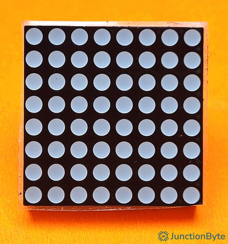
LED matrices are available in different grid sizes, but the 8×8 format is quite popular. This arrangement contains 64 LEDs.
How Does an 8×8 LED Matrix Work?
An 8×8 LED matrix consists of 64 LEDs arranged in 8 rows and 8 columns. Each LED sits at an intersection of one row and one column. This arrangement is identical to the 4×4 Matrix Keypad that we saw in a previous guide.
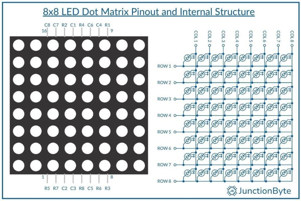
With this design, we can efficiently control all the 64 LEDs using a limited number of connections. Instead of wiring each LED separately, the matrix groups them into shared connections.
A microcontroller or driver chip sends signals that determine which LEDs light up. Every row and column connects to a dedicated pin. To activate a specific LED, we just need to supply voltage to the corresponding row and ground the associated column.
LED Addressing Using Row-Column Scanning
To control an LED matrix efficiently, we often use a technique called row-column scanning in the microcontroller’s software. In this method, we activate one row at a time while cycling through the columns. By rapidly switching rows and columns, the display appears continuous to our eyes.
The scanning process repeats multiple times per second, usually at a refresh rate above 50Hz. Higher refresh rates reduce flickering and improve visibility. Driver chips like the MAX7219 simplify this process by handling the scanning automatically. This reduces the workload on the microcontroller.
A Brief Note on MAX7219 IC
The MAX7219 integrated circuit is a serial-input/output common-cathode display driver. It can control up to 64 individual LEDs arranged in an 8×8 matrix or seven-segment displays.
It reduces the number of microcontroller pins required by handling decoding, multiplexing, current control, and brightness adjustment internally.
Additionally, we can daisy-chain multiple MAX7219 Modules to form a larger display without any impact on the number of microcontroller pins.
Working of MAX7219
The MAX7219 communicates using a serial interface similar to the Serial Peripheral Interface (SPI). It requires three input signals:
- Data In (DIN)
- Clock (CLK)
- Load (CS)
The microcontroller sends commands and display-data through the DIN pin while the CLK signal synchronizes the data.
The CS pin, also known as LOAD, determines when the MAX7219 latches the received data. When CS is HIGH, the chip ignores incoming data. Once CS goes LOW, the MAX7219 accepts commands and updates the display.
There is also the DOUT pin that allows daisy-chaining multiple MAX7219 ICs for larger displays.
The MAX7219 receives 16-bit commands, where the first eight bits specify the target register and the next eight bits contain the data. Various registers control different functions, including brightness, scan limits, and LED states.
For example, to control LEDs on the first row, the microcontroller must send the corresponding digit data to the correct register. The MAX7219 stores this data in its internal memory and updates the LED matrix accordingly.
MAX7219 Registers
As I mentioned in the previous section, the MAX7219 LED driver contains several control registers that manage display settings and data storage.
The following table summarizes the registers of the MAX7219 LED driver.
| Register Name | Address (Hex) | Accepted Values | Description |
| Decode Mode | 0x09 | 0x00 – No decode, for LED matrix0xFF – Full BCD decode for digits 0–70×01 to 0x07 – Selective BCD decoding for specific digits | Controls whether input data is interpreted as raw binary or BCD for seven-segment displays. For LED matrices, this should always be 0x00. |
| Intensity (Brightness Control) | 0x0A | 0x00 – Lowest brightness0x0F – Highest brightness | Adjusts the LED brightness by modifying the PWM duty cycle. Higher values increase brightness. |
| Scan Limit | 0x0B | 0x00 – Only digit/row 0 active0x07 – All digits/rows active | Defines the number of active digits (or rows in LED matrices). Setting it to 0x07 enables all eight rows. |
| Shutdown | 0x0C | 0x00 – Display off, retains data0x01 – Normal operation | Controls power to the display. The 0x00 value puts the display in power-saving mode without erasing stored data. |
| Display Test | 0x0F | 0x01 – All LEDs ON at full brightness0x00 – Normal operation | Used for diagnostics. Setting 0x01 lights up all LEDs to test functionality. It should be set to 0x00 in normal operation. |
| Data Registers | 0x01 to 0x08 | 0x00 to 0xFF – 8-bit data for each row | Stores the LED data for each row (or digit in a seven-segment display). Each bit controls an individual LED in a row. |
MAX7219 LED Dot Matrix Module
The MAX7219 LED Dot Matrix Display Module is a PCB with all the necessary components such as the MAX7219 IC, mounting points for the 8×8 LED matrix, and pins for connecting to power and microcontroller.
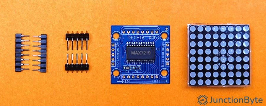
Speaking of pins, the MAX7219 module has five primary control pins for communicating with a microcontroller. These pins include VCC, GND, DIN, CS, CLK, and DOUT.
- VCC (Power Supply): This pin receives the operating voltage, typically 5V.
- GND (Ground): This pin connects to the microcontroller’s ground for proper circuit operation.
- DIN (Data In): This pin receives serial data from the microcontroller.
- CS (Chip Select): This pin enables or disables communication with the MAX7219 module.
- CLK (Clock): This pin receives clock pulses that synchronize data transmission. Each clock pulse shifts one bit of data into the module.
- DOUT (Data Out): Data received at DIN shifts through the current module and exits through DOUT. This pin outputs serial data for cascading multiple MAX7219 modules. DOUT of one module links to DIN of the next.
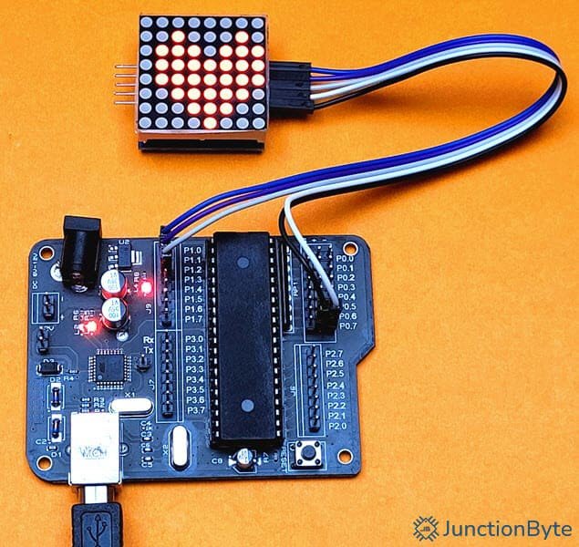
Hardware Setup for Interfacing MAX7219 LED Dot Matrix Display with 8051 Microcontroller
Components Needed
- 8051 Microcontroller Development Board
- MAX7219 LED Dot Matrix Display
- Jumper Wires
Steps for Writing the Firmware for 8051
Port Configuration
First, we have to assign the serial communication lines to specific 8051 pins. The following pin mapping works well:
- P1.2 → DIN (Data In)
- P1.1 → CS (Chip Select)
- P1.0 → CLK (Clock)
Initializing MAX7219
Before sending display data, the MAX7219 requires proper initialization. The microcontroller must configure several registers to activate the display and define operating parameters.
- Shutdown Register: Activates or deactivates the display. Set this to 0x01 to turn it on.
- Scan Limit Register: Defines the number of active rows. For an 8×8 display, set this to 0x07.
- Decode Mode Register: Configures digit decoding. Set 0x00 for a raw LED matrix.
- Intensity Register: Adjusts brightness. Set a value between 0x00 (minimum) and 0x0F (maximum).
Each command follows the 16-bit data format, where the first byte represents the register address and the second byte contains the data.
Data Transmission
After initializing the MAX7219, the microcontroller can send data to control individual LEDs. The process of writing data involves three main steps:
- Set CS Low – Activate the MAX7219 for data reception.
- Send 16 Bits – Transmit the register address and data sequentially.
- Set CS High – Latch the data into the MAX7219.
We can implement a software function that performs this operation by shifting out each bit while toggling the clock line.
Code for Interfacing MAX7219 LED Matrix with 8051 Microcontroller
#include <reg52.h>

sbit DIN = P1^2;   /* Serial Data Input */
sbit CS = P1^1;    /* Chip Select (active low) */
sbit CLK = P1^0;   /* Serial Clock */

void delay_ms(unsigned int ms)
{
  unsigned int i, j;
  for (i = 0; i < ms; i++)
  {
    for (j = 0; j < 123; j++); /* Approximate 1ms Delay */
  }
}


/* Send 16-Bit Data to the MAX7219 Module */
/* First 8-Bit Address and next, 8-Bit Data */
void sendData(unsigned char address, unsigned char datax)
{
  unsigned char i;

  CS = 0;  /* Start Data Transmission */

  /* Send Address Data to MAX7219 */
  for (i = 0; i < 8; i++)
  {
    DIN = (address & 0x80) ? 1 : 0;
    CLK = 1;
    delay_ms(1);
    CLK = 0;
    address <<= 1;
  }
  /* Send Actual Data to MAX7219 */

  for (i = 0; i < 8; i++)
  {
    DIN = (datax & 0x80) ? 1 : 0;
    CLK = 1;
    delay_ms(1);
    CLK = 0;
    datax <<= 1;
  }

  CS = 1;  /* Latch the Data */
  delay_ms(1);
}

void initMAX7219()
{
  /* Initialize the MAX7219 Module */
  sendData(0x09, 0x00);  /* Decode Mode OFF */
  sendData(0x0A, 0x03);  /* Lower Intensity Level */
  sendData(0x0B, 0x07);  /* Scan Limit: Display all 8 Rows */
  sendData(0x0C, 0x01);  /* Power ON */
}

/* Clear the MAX7219 Buffer */
void clearMAX7219()
{
  unsigned char row;
  for (row = 1; row <= 8; row++)
  {
    sendData(row, 0x00);  /* Send Blank Data the MAX7219 Unit */
  }
}

void main()
{
  initMAX7219();
  clearMAX7219();  /* Turn OFF all LEDs */
  sendData(0x01, 0xFF);  /* Turn ON all LEDs in Row 1 */
  delay_ms(1000);
  sendData(0x01, 0x00);  /* Turn OFF all LEDs in Row 1 */
  delay_ms(1000);

  while(1)
  {
    sendData(0x01, 0xAA);
    delay_ms(1000);
    sendData(0x01, 0x55);
    delay_ms(1000);
  }
}
Displaying Characters on MAX7219 using 8051
For the next example, I will show you how to display basic alphanumeric characters as well as some symbols. I created a character map for all the alphabets (both upper case and lower case), numbers (0 to 9), ASCII Symbols, and some custom icons (heart, circle, etc.).
Sadly, the low memory of the 8051 Microcontroller is a serious limitation as the code will not compile if I include all the 100+ characters. As per my testing, we can include up to 14 characters.
You can use the “font” file and comment out all the unnecessary characters and include the 12 or 14 characters that you want to use.
Here is the ‘font.h’ file. You have to include this file in your project.
const char PATTERN[][8] = {
  /*{0x00, 0x3C, 0x66, 0x6E, 0x76, 0x66, 0x66, 0x3C}, // 0
  {0x00, 0x18, 0x18, 0x38, 0x18, 0x18, 0x18, 0x7E}, // 1
  {0x00, 0x3C, 0x66, 0x06, 0x0C, 0x30, 0x60, 0x7E}, // 2
  {0x00, 0x3C, 0x66, 0x06, 0x1C, 0x06, 0x66, 0x3C}, // 3
  {0x00, 0x0C, 0x1C, 0x2C, 0x4C, 0x7E, 0x0C, 0x0C}, // 4
  {0x00, 0x7E, 0x60, 0x7C, 0x06, 0x06, 0x66, 0x3C}, // 5
  {0x00, 0x3C, 0x66, 0x60, 0x7C, 0x66, 0x66, 0x3C}, // 6
  {0x00, 0x7E, 0x66, 0x0C, 0x0C, 0x18, 0x18, 0x18}, // 7
  {0x00, 0x3C, 0x66, 0x66, 0x3C, 0x66, 0x66, 0x3C}, // 8
  {0x00, 0x3C, 0x66, 0x66, 0x3E, 0x06, 0x66, 0x3C}, // 9*/

  /*{0x00, 0x3C, 0x66, 0x66, 0x7E, 0x66, 0x66, 0x66}, // A
  {0x00, 0x7C, 0x66, 0x66, 0x7C, 0x66, 0x66, 0x7C}, // B
  {0x00, 0x3C, 0x66, 0x60, 0x60, 0x60, 0x66, 0x3C}, // C
  {0x00, 0x7C, 0x66, 0x66, 0x66, 0x66, 0x66, 0x7C}, // D
  {0x00, 0x7E, 0x60, 0x60, 0x7C, 0x60, 0x60, 0x7E}, // E
  {0x00, 0x7E, 0x60, 0x60, 0x7C, 0x60, 0x60, 0x60}, // F
  {0x00, 0x3C, 0x66, 0x60, 0x60, 0x6E, 0x66, 0x3C}, // G
  {0x00, 0x66, 0x66, 0x66, 0x7E, 0x66, 0x66, 0x66}, // H
  {0x00, 0x3C, 0x18, 0x18, 0x18, 0x18, 0x18, 0x3C}, // I
  {0x00, 0x1E, 0x0C, 0x0C, 0x0C, 0x6C, 0x6C, 0x38}  // J
}; */
  /*{0x00, 0x66, 0x6C, 0x78, 0x70, 0x78, 0x6C, 0x66}, // K
  {0x00, 0x60, 0x60, 0x60, 0x60, 0x60, 0x60, 0x7E}, // L
  {0x00, 0x63, 0x77, 0x7F, 0x6B, 0x63, 0x63, 0x63}, // M
  {0x00, 0x63, 0x73, 0x7B, 0x6F, 0x67, 0x63, 0x63}, // N
  {0x00, 0x3C, 0x66, 0x66, 0x66, 0x66, 0x66, 0x3C}, // O
  {0x00, 0x7C, 0x66, 0x66, 0x66, 0x7C, 0x60, 0x60}, // P
  {0x00, 0x3C, 0x66, 0x66, 0x66, 0x6E, 0x3C, 0x06}, // Q
  {0x00, 0x7C, 0x66, 0x66, 0x7C, 0x78, 0x6C, 0x66}, // R
  {0x00, 0x3C, 0x66, 0x60, 0x3C, 0x06, 0x66, 0x3C}, // S
  {0x00, 0x7E, 0x5A, 0x18, 0x18, 0x18, 0x18, 0x18}, // T
  {0x00, 0x66, 0x66, 0x66, 0x66, 0x66, 0x66, 0x3E}, // U
  {0x00, 0x66, 0x66, 0x66, 0x66, 0x66, 0x3C, 0x18}, // V
  {0x00, 0x63, 0x63, 0x63, 0x6B, 0x7F, 0x77, 0x63}, // W
  {0x00, 0x63, 0x63, 0x36, 0x1C, 0x36, 0x63, 0x63}, // X
  {0x00, 0x66, 0x66, 0x66, 0x3C, 0x18, 0x18, 0x18}, // Y
  {0x00, 0x7E, 0x06, 0x0C, 0x18, 0x30, 0x60, 0x7E}  // Z
};*/
 /* {0x00, 0x00, 0x00, 0x00, 0x00, 0x00, 0x00, 0x00}, // Blank

  {0x00, 0x00, 0x00, 0x3C, 0x06, 0x3E, 0x66, 0x3E}, // a
  {0x00, 0x60, 0x60, 0x60, 0x7C, 0x66, 0x66, 0x7C}, // b
  {0x00, 0x00, 0x00, 0x3C, 0x66, 0x60, 0x66, 0x3C}, // c
  {0x00, 0x06, 0x06, 0x06, 0x3E, 0x66, 0x66, 0x3E}, // d
  {0x00, 0x00, 0x00, 0x3C, 0x66, 0x7E, 0x60, 0x3C}, // e
  {0x00, 0x1C, 0x36, 0x30, 0x30, 0x7C, 0x30, 0x30}, // f
  {0x00, 0x00, 0x3E, 0x66, 0x66, 0x3E, 0x06, 0x3C}, // g
  {0x00, 0x60, 0x60, 0x60, 0x7C, 0x66, 0x66, 0x66}, // h
  {0x00, 0x00, 0x00, 0x18, 0x00, 0x18, 0x18, 0x18}, // i
  {0x00, 0x0C, 0x00, 0x0C, 0x0C, 0x6C, 0x6C, 0x38}, // j
  {0x00, 0x60, 0x60, 0x66, 0x6C, 0x78, 0x6C, 0x66}, // k
  {0x00, 0x18, 0x18, 0x18, 0x18, 0x18, 0x18, 0x18}, // l
  {0x00, 0x00, 0x00, 0x63, 0x77, 0x7F, 0x6B, 0x6B}, // m
  {0x00, 0x00, 0x00, 0x7C, 0x7E, 0x66, 0x66, 0x66}, // n
  {0x00, 0x00, 0x00, 0x3C, 0x66, 0x66, 0x66, 0x3C}, // o
  {0x00, 0x00, 0x00, 0x7C, 0x66, 0x66, 0x7C, 0x60}, // p
  {0x00, 0x00, 0x00, 0x3C, 0x6C, 0x6C, 0x3C, 0x1D}, // q
  {0x00, 0x00, 0x00, 0x7C, 0x66, 0x66, 0x60, 0x60}, // r
  {0x00, 0x00, 0x00, 0x3E, 0x40, 0x3C, 0x02, 0x7C}, // s
  {0x00, 0x00, 0x00, 0x18, 0x18, 0x7E, 0x18, 0x18}, // t
  {0x00, 0x00, 0x00, 0x66, 0x66, 0x66, 0x66, 0x3E}, // u
  {0x00, 0x00, 0x00, 0x00, 0x66, 0x66, 0x3C, 0x18}, // v
  {0x00, 0x00, 0x00, 0x63, 0x6B, 0x6B, 0x6B, 0x3E}, // w
  {0x00, 0x00, 0x00, 0x66, 0x3C, 0x18, 0x3C, 0x66}, // x
  {0x00, 0x00, 0x00, 0x66, 0x66, 0x3E, 0x06, 0x3C}, // y
  {0x00, 0x00, 0x00, 0x3C, 0x0C, 0x18, 0x30, 0x3C} // z
};*/

  /*{0x00, 0x00, 0x08, 0x08, 0x3E, 0x08, 0x08, 0x00}, // +
  {0x00, 0x00, 0x00, 0x00, 0x3C, 0x00, 0x00, 0x00}, // -
  {0x00, 0x00, 0x36, 0x1C, 0x7F, 0x1C, 0x36, 0x00}, // *
  {0x00, 0x00, 0x06, 0x0C, 0x18, 0x30, 0x60, 0x00}, // /
  {0x00, 0x60, 0x66, 0x0C, 0x18, 0x30, 0x66, 0x06}, // %
  {0x00, 0x00, 0x00, 0x3C, 0x00, 0x3C, 0x00, 0x00}, // =
  {0x00, 0x00, 0x00, 0x3A, 0x6C, 0x00, 0x00, 0x00}, // ~
  {0x00, 0x08, 0x14, 0x22, 0x41, 0x00, 0x00, 0x00}, // ^
  {0x00, 0x06, 0x0C, 0x18, 0x30, 0x18, 0x0C, 0x06}, // <
  {0x00, 0x60, 0x30, 0x18, 0x0C, 0x18, 0x30, 0x60}, // >
  {0x00, 0x06, 0x0C, 0x18, 0x18, 0x18, 0x0C, 0x06}, // (
  {0x00, 0x60, 0x30, 0x18, 0x18, 0x18, 0x30, 0x60}, // )
  {0x00, 0x1E, 0x18, 0x18, 0x18, 0x18, 0x18, 0x1E}, // [
  {0x00, 0x78, 0x18, 0x18, 0x18, 0x18, 0x18, 0x78}, // ]
  {0x00, 0x0E, 0x18, 0x18, 0x30, 0x18, 0x18, 0x0E}, // {
  {0x00, 0x70, 0x18, 0x18, 0x0C, 0x18, 0x18, 0x70}, // }
  {0x00, 0x00, 0x00, 0x00, 0x00, 0x00, 0x60, 0x60}, // .
  {0x00, 0x00, 0x18, 0x18, 0x00, 0x18, 0x18, 0x00}, // :
  {0x00, 0x00, 0x18, 0x18, 0x00, 0x18, 0x18, 0x30}, // ;
  {0x00, 0x00, 0x00, 0x00, 0x30, 0x30, 0x30, 0x60}, // ,
  {0x00, 0x18, 0x3C, 0x3C, 0x18, 0x18, 0x00, 0x18}, // !
  {0x00, 0x3C, 0x66, 0x06, 0x1C, 0x18, 0x00, 0x18}, // ?
  {0x00, 0x38, 0x44, 0x5C, 0x58, 0x42, 0x3C, 0x00}, // @
  {0x00, 0x3C, 0x66, 0x3C, 0x28, 0x65, 0x66, 0x3F}, // &
  {0x00, 0x08, 0x1E, 0x20, 0x1C, 0x02, 0x3C, 0x08}, // $
  {0x00, 0x36, 0x36, 0x7F, 0x36, 0x7F, 0x36, 0x36}, // #*/


  {0x00, 0x08, 0x1C, 0x3E, 0x7F, 0x1C, 0x1C, 0x1C}, // Up Arrow
  {0x00, 0x1C, 0x1C, 0x1C, 0x7F, 0x3E, 0x1C, 0x08}, // Down Arrow
  {0x00, 0x08, 0x0C, 0x7E, 0x7F, 0x7E, 0x0C, 0x08}, // Right Arrow
  {0x00, 0x08, 0x18, 0x3F, 0x7F, 0x3F, 0x18, 0x08}, // Left Arrow
  {0x00, 0x08, 0x1C, 0x1C, 0x3E, 0x3E, 0x7F, 0x7F}, // Pyramid
  {0x00, 0x7F, 0x7F, 0x3E, 0x3E, 0x1C, 0x1C, 0x08}, // Inverted Pyramid
  {0x00, 0x60, 0x78, 0x7E, 0x7F, 0x7E, 0x78, 0x60}, // Right Pyramid
  {0x00, 0x03, 0x0F, 0x3F, 0x3F, 0x1F, 0x0F, 0x03}, // Left Pyramid
  {0x00, 0x3E, 0x41, 0x55, 0x41, 0x55, 0x49, 0x3E}, // Face 1
  {0x00, 0x3E, 0x7F, 0x6B, 0x7F, 0x6B, 0x77, 0x3E},  // Face 2
  {0x00, 0x22, 0x77, 0x7F, 0x7F, 0x3E, 0x1C, 0x08}, // Heart
  {0x00, 0x08, 0x1C, 0x3E, 0x7F, 0x3E, 0x1C, 0x08}, // Rhombus
  {0x00, 0x08, 0x1C, 0x2A, 0x7F, 0x2A, 0x08, 0x1C}, // Spade 1
  {0x00, 0x08, 0x1C, 0x3E, 0x7F, 0x3E, 0x08, 0x1C} // Spade 2
};

  /*{0x00, 0x00, 0x1C, 0x3E, 0x3E, 0x3E, 0x1C, 0x00}, // Full Circle
  {0xFF, 0xFF, 0xE3, 0xC1, 0xC1, 0xC1, 0xE3, 0xFF}, // Inverted Full Circle
  {0x00, 0x00, 0x1C, 0x22, 0x22, 0x22, 0x1C, 0x00}, // Circle
  {0xFF, 0xFF, 0xE3, 0xDD, 0xDD, 0xDD, 0xE3, 0xFF}, // Inverted Circle
  {0x00, 0x0F, 0x03, 0x05, 0x39, 0x48, 0x48, 0x30}, // Male
  {0x00, 0x08, 0x3E, 0x08, 0x1C, 0x22, 0x22, 0x1C}, // Female
  {0x00, 0x18, 0x14, 0x10, 0x10, 0x30, 0x70, 0x60}, // Music 1
  {0x00, 0x0F, 0x19, 0x11, 0x13, 0x37, 0x76, 0x60}, // Music 2
  {0x00, 0x08, 0x2A, 0x1C, 0x77, 0x1C, 0x2A, 0x08}, // Snowflake
  {0x00, 0x08, 0x1C, 0x2A, 0x08, 0x2A, 0x1C, 0x08}, // Double Arrow
  {0x00, 0x66, 0x66, 0x66, 0x66, 0x00, 0x66, 0x66}, // Symbol 1
  {0x00, 0x00, 0x14, 0x22, 0x7F, 0x22, 0x14, 0x00}, // Side Double Arrow
  {0x00, 0x36, 0x36, 0x14, 0x00, 0x00, 0x00, 0x00}, // Symbol 2
  {0x00, 0x00, 0x60, 0x30, 0x18, 0x0C, 0x06, 0x00}, // '\'
  {0x00, 0x0C, 0x0C, 0x06, 0x00, 0x00, 0x00, 0x00}, // `
  {0x00, 0x18, 0x18, 0x18, 0x30, 0x00, 0x00, 0x00}, // '
  {0x00, 0x08, 0x1C, 0x36, 0x63, 0x41, 0x41, 0x7F}  // Home
};*/

const int PATTERN_LEN = sizeof(PATTERN)/8;
As far as the main code is concerned, I’m using the ‘font.h’ file to display 14 special symbols in a loop. You can see the active symbols in the ‘font.h’ file which are uncommented.
#include <reg52.h>
#include "font.h"

sbit DIN = P1^2;   /* Serial Data Input */
sbit CS = P1^1;    /* Chip Select (active low) */
sbit CLK = P1^0;   /* Serial Clock */

void delay_ms(unsigned int ms)
{
  unsigned int i, j;
  for (i = 0; i < ms; i++)
  {
    for (j = 0; j < 123; j++); /* Approximate 1ms Delay */
  }
}

/* Send 16-Bit Data to the MAX7219 Module */
/* First 8-Bit Address and next, 8-Bit Data */
void sendData(unsigned char address, unsigned char datax)
{
  unsigned char i;

  CS = 0;  /* Start Data Transmission */

  /* Send Address Data to MAX7219 */
  for (i = 0; i < 8; i++)
  {
    DIN = (address & 0x80) ? 1 : 0;
    CLK = 1;
    delay_ms(1);
    CLK = 0;
    address <<= 1;
  }
  /* Send Actual Data to MAX7219 */

  for (i = 0; i < 8; i++)
  {
    DIN = (datax & 0x80) ? 1 : 0;
    CLK = 1;
    delay_ms(1);
    CLK = 0;
    datax <<= 1;
  }

  CS = 1;  /* Latch the Data */
  delay_ms(1);
}

void initMAX7219()
{
  /* Initialize the MAX7219 Module */
  sendData(0x09, 0x00);  /* Decode Mode OFF */
  sendData(0x0A, 0x01);  /* Lower Intensity Level */
  sendData(0x0B, 0x07);  /* Scan Limit: Display all 8 Rows */
  sendData(0x0C, 0x01);  /* Power ON */
}

/* Clear the MAX7219 Buffer */
void clearMAX7219()
{
  unsigned char row;
  for (row = 1; row <= 8; row++)
  {
    sendData(row, 0x00);  /* Send Blank Data the MAX7219 Unit */
  }
}

void displayPattern(unsigned char patternIndex)
{
  unsigned char row;
  for (row = 1; row <= 8; row++)
  {
    /* Send the corresponding row data for the Pattern */
    sendData(row, PATTERN[patternIndex][row-1]);
  }
}

void main()
{
  unsigned char num = 0;
  initMAX7219();
  clearMAX7219();  /* Turn OFF all LEDs */

  while(1)
  {
    displayPattern(num);  /* Display the current digit */
    delay_ms(1000);  /* Delay between digits */
    num++;  /* Increment the number */
    if (num > PATTERN_LEN-1)

      num = 0;  /* Reset to 0 after displaying all the characters */
  }
}
Cascading Multiple MAX7219 Modules
A single MAX7219 controls an 8×8 LED matrix, but multiple units can work together for larger displays. Cascading several modules can extend the display area and we can implement more complex animations and messages.
Connecting several MAX7219 modules in series is a simple process. The DOUT (Data Out) pin plays an important role when using multiple modules in a chain. Instead of wiring each module separately, a single microcontroller can control all connected modules by linking DOUT to DIN across modules.
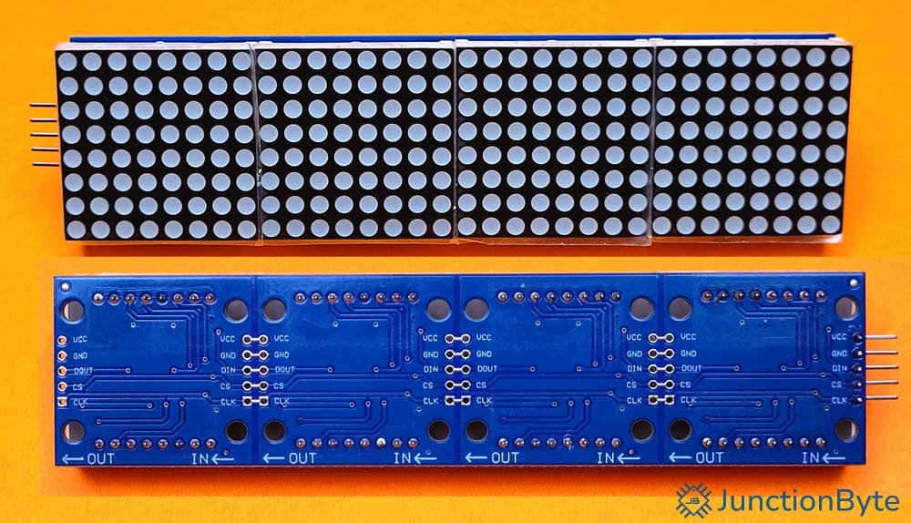
The DOUT pin of one unit connects to the DIN (Data In) pin of the next. The CLK (Clock) and CS (Chip Select) lines remain common across all modules.
Each module responds to data based on its position in the sequence. The first unit (closest to the microcontroller) processes the last data chunk, while the last unit (farthest from the microcontroller) displays the first set of values. We must write the software so that the data shifts correctly.
If you have a four-module setup, we need to send four sets of data to update all modules. The microcontroller transmits data in the following order:
- First Data Packet → Module 4
- Second Data Packet → Module 3
- Third Data Packet → Module 2
- Fourth Data Packet → Module 1
To display numbers 0 to 9 on the first module while keeping the others off, the microcontroller should send:
- Data for Modules 2, 3, and 4 as 0x00 (turning off LEDs).
- Data for Module 1 containing the required digit pattern.
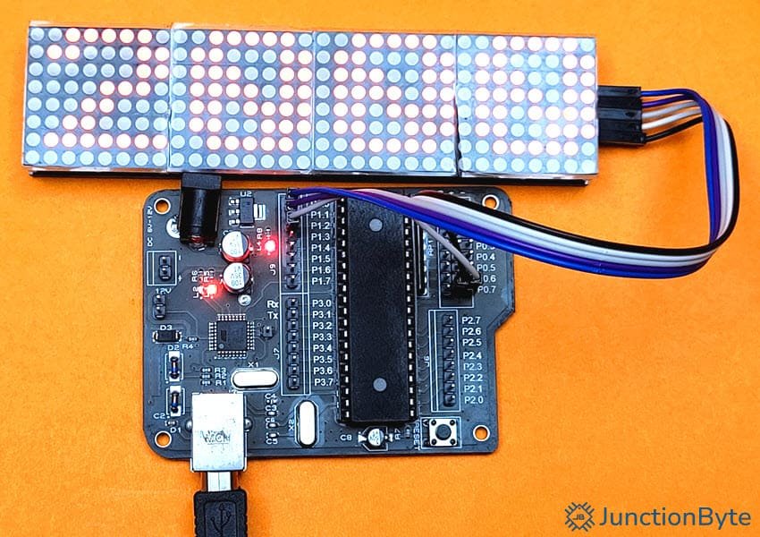
Code for 4-Channel MAX7219 LED Dot Matrix
I created a small example program for the 4-Channel MAX7219 LED Matrix Module. In this code, the LED Matrix displays numbers from 0 to 9,999 in a loop.
#include <reg52.h>

/* Pin Definitions */
sbit DIN = P1^2;  /* Data Input */
sbit CS  = P1^1;  /* Chip Select */
sbit CLK = P1^0;  /* Clock */

void delay_ms(unsigned int time)
{
  unsigned int i, j;
  for (i = 0; i < time; i++)
  {
    for (j = 0; j < 1275; j++);
  }
}

/* Digit Patterns for Digits 0 to 9 */
unsigned char digits[10][8] = {
    {0x3E, 0x63, 0x73, 0x7B, 0x6F, 0x67, 0x3E, 0x00}, // 0
    {0x0C, 0x1C, 0x3C, 0x0C, 0x0C, 0x0C, 0x3F, 0x00}, // 1
    {0x3E, 0x63, 0x03, 0x0E, 0x18, 0x30, 0x7F, 0x00}, // 2
    {0x3E, 0x63, 0x03, 0x1E, 0x03, 0x63, 0x3E, 0x00}, // 3
    {0x06, 0x0E, 0x1E, 0x36, 0x66, 0x7F, 0x06, 0x00}, // 4
    {0x7F, 0x60, 0x7E, 0x03, 0x03, 0x63, 0x3E, 0x00}, // 5
    {0x3E, 0x63, 0x60, 0x7E, 0x63, 0x63, 0x3E, 0x00}, // 6
    {0x7F, 0x63, 0x06, 0x0C, 0x18, 0x30, 0x30, 0x00}, // 7
    {0x3E, 0x63, 0x63, 0x3E, 0x63, 0x63, 0x3E, 0x00}, // 8
    {0x3E, 0x63, 0x63, 0x3F, 0x03, 0x63, 0x3E, 0x00}  // 9
};

/* Function to Send 16-Bits of Address and Data */
void send_16bits(unsigned int datax)
{
  unsigned char i;
  unsigned int j = 0;
  for(i = 16; i > 0; i--)
  {
    DIN = (datax >> (i - 1)) & 0x01;  /* MSB First */
    CLK = 1;                         /* Clock Rising Edge */
    CLK = 0;                         /* Clock Falling Edge */
  }
}

/* Function to Send Commands to All 4 Cascaded MAX7219 */
void send_MAX7219(unsigned int cmd4, unsigned int cmd3, unsigned int cmd2, unsigned int cmd1)
{
  CS = 0;  /* Begin Transmission */

  /* Send commands in order: Channel4, Channel3, Channel2, Channel1 */
  send_16bits(cmd4);
  send_16bits(cmd3);
  send_16bits(cmd2);
  send_16bits(cmd1);

  CS = 1;  /* Latch Data */
}

void displayNumber(unsigned int number)
{
  unsigned char thousands, hundreds, tens, ones;
  unsigned int module1_data, module2_data, module3_data, module4_data;
  unsigned char row;

  /* Extract the Digits */
  thousands = number / 1000;        /* Extract the thousands digit */
  hundreds = (number % 1000) / 100; /* Extract the hundreds digit */
  tens = (number % 100) / 10;       /* Extract the tens digit */
  ones = number % 10;               /* Extract the ones digit */

  for (row = 0; row < 8; row++)
  {
    module4_data = ((row+1) << 8) | digits[thousands][row];
    module3_data = ((row+1) << 8) | digits[hundreds][row];
    module2_data = ((row+1) << 8) | digits[tens][row];
    module1_data = ((row+1) << 8) | digits[ones][row];

    send_MAX7219(module4_data, module3_data, module2_data, module1_data);
  }
}

void main()
{
  unsigned int num = 0;
  /* Initialize All MAX7219 Controllers */

  /* Set Scan Limit to 8 Rows (0x0B07) */
  send_MAX7219(0x0B07, 0x0B07, 0x0B07, 0x0B07);

  /* Disable Decode Mode (0x0900) */
  send_MAX7219(0x0900, 0x0900, 0x0900, 0x0900);

  /* Set Low Intensity (0x0A01) */
  send_MAX7219(0x0A01, 0x0A01, 0x0A01, 0x0A01);

  /* Disable Test Mode (0x0F00) */
  send_MAX7219(0x0F00, 0x0F00, 0x0F00, 0x0F00);

  /* Turn OFF Channels (Shutdown Mode: 0x0C00) */
  /* Keep Channels Active (Normal Mode: 0x0C01) */
  send_MAX7219(0x0C01, 0x0C01, 0x0C01, 0x0C01);

  while(1)
  {
    displayNumber(num);  /* Display current number */
    num++;  /* Increment number */
    if (num > 9999) num = 0;  /* Reset to 0 after 9999 */
    delay_ms(10);  /* Delay for 1 second */
  }
}
Here’s what the output looks like.
Conclusion
A complete beginner’s guide on how to Interface MAX7219 LED Dot Matrix Display with an 8051 Microcontroller. I explained the working of a typical 8×8 LED Dot Matrix, the internal structure i.e., how the LEDs are laid out, and the importance of the driver ICs such as the MAX7219.
Later, I also gave example codes for interfacing a generic MAX7219 LED Matrix Module with an 8051 Microcontroller. Additionally, I also provided sample code for the 4-Channel Cascaded version of the MAX7219 LED Matrix.
Using this information, you can build a wide variety of applications using the MAX7219 8×8 LED Dot Matrix Display.