In a previous guide, we saw one of the widely-used serial communication protocols in the world of embedded systems: I2C (I2C). While I2C is great for situations where the microcontroller needs to communicate with multiple devices with simple wiring (needs only two wires), it has some major flaws. One flaw that has a significant impact is the data transfer speed of I2C. If you want to interface displays or data storage devices, then you need something faster than what I2C offers. This is where SPI or Serial Peripheral Interface comes into play. In this 8051 Microcontroller SPI guide, I will discuss everything you need to know about SPI and how you can implement SPI Communication in 8051 Microcontroller.
First, I will explain some basics of SPI Protocol (key components, communication lines, modes, etc.). Then I will show how to implement software-based SPI in microcontrollers such as oldschool 8051. Later, we will use this knowledge to write a driver for SPI as well as some basic applications that use SPI Communication.
A Brief Note on SPI (Serial Peripheral Interface)
What is SPI?
SPI, or Serial Peripheral Interface, is a synchronous serial communication protocol used for short-distance communication between microcontrollers and peripheral devices. The term “synchronous” means that data transfers occur with a shared clock signal. Unlike asynchronous protocols like UART, SPI does not require start and stop bits.
SPI also supports full-duplex communication which enables data to flow in both directions simultaneously. As a result, devices can send and receive data at the same time.
Like I2C, SPI also follows a “Master – Slave” configuration. Here, one device acts as the bus master and controls the communication. It generates the clock signal and initiates data transfers, while the slave responds to the master’s commands.
Many electronic components, including sensors, memory chips, and displays, use SPI for rapid data transfer. Devices like SD cards, OLED, and LCD screens use SPI to send and receive large amounts of data efficiently.
SPI Hardware Lines
SPI uses four primary hardware lines for communication:
- SCK (or SCLK)
- MOSI
- MISO
- SS
The master generates the SCK signal, which synchronizes data transmission between devices. Every clock pulse triggers the transfer of a single data bit. The speed of the SCLK determines the rate at which information moves through the SPI bus.
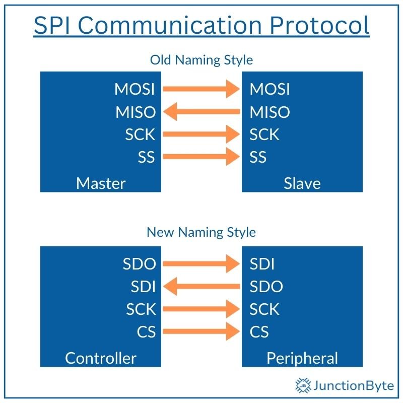
MOSI (Master Out, Slave In) carries data from the master to the slave. During each clock cycle, the master sends one bit through this line. MISO (Master In, Slave Out) transmits data from the slave back to the master. If a slave does not need to send data, this line remains inactive. When active, the slave places data on MISO in sync with the clock pulses.
Each slave connects to the master through a separate SS/CS (Slave Select/Chip Select) line. The master uses this line to activate a specific slave device. When the master pulls a slave’s SS pin low, the slave begins communication. If multiple slaves exist, the master toggles their respective chip select lines as needed.
Clock Polarity (CPOL) and Phase (CPHA) Settings
SPI supports different clock configurations based on two parameters: clock polarity (CPOL) and clock phase (CPHA). These parameters determine how data synchronizes with the clock pulses.
CPOL defines the idle state of the clock. A CPOL value of 0 keeps the clock low when inactive, while a value of 1 keeps it high.
CPHA controls when data gets sampled. A CPHA value of 0 samples data at the leading clock edge, while a value of 1 samples it at the trailing edge.
Devices must share the same CPOL and CPHA settings to communicate properly.
SPI Data Transmission Process
During SPI communication, data shifts in and out of devices in a serial fashion. The SPI communication is basically two shift registers transmitting data bit by bit. The protocol typically transmits data in 8-bit frames, with the Most Significant Bit (MSB) sent first.
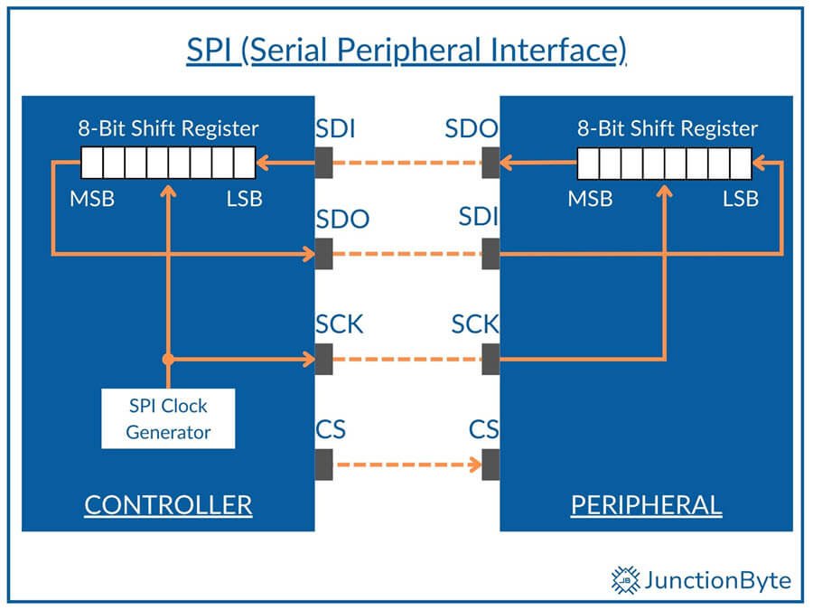
However, some devices may use the Least Significant Bit (LSB) first, depending on their configuration. The master and slave must agree on the bit order to avoid miscommunication.
With proper clock synchronization, both devices can interpret the data correctly. The master generates the clock signal, and the slave uses it to sample incoming data. Each clock cycle corresponds to one bit of data.
New SPI Signal Names
The names ‘Master’ and ‘Slave’ are being phased out. Instead, many publications are following the ‘Controller’ and ‘Peripheral’ terminology.
As far as the hardware lines are concerned, there are several accepted conventions but the most popular one is:
- SDO (Serial Data Out)
- SDI (Serial Data In)
- CS (Chip Select)
- SCK (Serial Clock)
Does an 8051 Microcontroller Have SPI?
If you remember the 8051 Microcontroller I2C Guide, I said the basic 8051 Microcontroller doesn’t have any built-in I2C hardware. Then what about SPI? Most standard 8051 microcontrollers do not include dedicated SPI hardware.
We must create SPI functionality using software-based techniques to communicate with external devices. This approach, known as ‘bit-banging,’ allows us to implement SPI communication using general-purpose I/O (GPIO) pins of the 8051 Microcontroller.
Using bit-banging, we can allow SPI communication to work on any available digital pins. In this process, we will be manually controlling the clock and data lines of the SPI with the help of simple software routines to simulate SPI behavior.
Although this method increases CPU workload, it enables communication with SPI peripherals without requiring any additional or external hardware.
How to Implement SPI Communication in 8051?
Assign Pins for SCK, SDO, SDI, and CS
As the 8051 microcontroller does not include dedicated SPI pins, our first step is to assign GPIO pins for the four SPI lines.
Write SPI Routines Using Bit-Banging
We can write three basic functions for SPI communication:
- SPI_Init()
- SPI_Send()
- SPI_Receive()
The ‘SPI_Init()’ function can configure the selected GPIO pins as input or output based on their roles. SCK, SDO, and CS must be outputs, while SDI is an input.
To transmit data over SPI, the ‘Controller’ must shift each bit and send it over SDO. The ‘SPI_Send()’ function first pulls the CS pin low to activate the target ‘Peripheral’ device. Then, it sends one bit at a time through the SDO line while toggling the clock.
Each clock pulse signals the ‘Peripheral’ to read the current bit on SDO (SDI on Peripheral). After sending all bits, the function pulls CS high to complete the transfer and release the ‘Peripheral.’
Receiving data from a ‘Peripheral’ follows a similar process. The ‘SPI_Receive()’ function starts by selecting the device through the CS pin. The microcontroller generates clock pulses while reading each incoming bit on SDI.
After detecting a bit, the function shifts it into a variable to reconstruct the original byte. This process continues until the function receives all eight bits. Once the transfer completes, the program pulls CS high and returns the received byte.
If the system has multiple SPI devices, then each ‘Peripheral’ requires an individual CS pin connected to the microcontroller. Before communication starts, the program must select the correct device by pulling its CS pin low.
SPI Timing Delays
Proper timing between clock pulses is important to prevent transmission errors. Some SPI devices operate at lower speeds and require precise delays. The microcontroller must maintain stable timing for both sending and receiving data.
Adding short delays between clock transitions helps match the timing of slower peripherals. We can use a delay function with a simple loop or the ‘NOP’ instruction, test different delay values, and fine-tune the timings.
8051 Microcontroller SPI Example Code
The following program demonstrates basic 8051 SPI communication using bit-banging. The program transmits one byte and reads a response from the ‘Peripheral.’
Code
Demo of 8051 Microcontroller SPI Implementation
We can test the previous code by interfacing the 8051 with a 25AA640A SPI EEPROM. The ‘25AA640A’ is a popular EEPROM IC from Microchip that communicates over SPI. It supports a clock speed of up to 10 MHz and has a capacity of 64 Kbits.