In a previous guide, we saw how to interface a 16×2 character LCD with an 8051 Microcontroller. The advantage of such LCD modules is that you can display all the characters and symbols in the ASCII table and some more. What if your application is much simpler and needs displaying only numbers (and to some extent a few alphabets)? This is where 7-Segment Displays come in handy. As the name suggests, a Seven Segment Display consists of seven segments (with individual LEDs) arranged in the shape of the number eight (8). By selectively lighting these segments, we can form digits from 0 to 9 and some basic letters. In this guide, I’ll explain everything you need to know on how to interface a 7-Segment Display with an 8051 Microcontroller.
In the process, I will first talk a little bit about 7-Segment Displays including their working and types. Then, we will move on to building a circuit for interfacing a Common Cathode type Seven Segment LED Display with the 8051 Microcontroller (AT89S52) and writing example codes and drivers.
Last but not least, I will also explain how to interface a 4-Channel 7-Segment Display with an 8051 Microcontroller.
This topic is fairly independent and you don’t need knowledge about other peripherals of the 8051 Microcontroller. However, if you are new to programming an 8051 Microcontroller, here’s a guide on ‘How to Program 8051 Microcontroller in Keil µVision?’
What is a Seven Segment Display?
A Seven Segment Display (or 7-Segment Display) is an electronic display device that shows numeric digits using seven individual LEDs arranged in a figure-eight pattern. These segments, which are the seven rectangular blocks of the figure-eight, form numbers by lighting specific combinations.
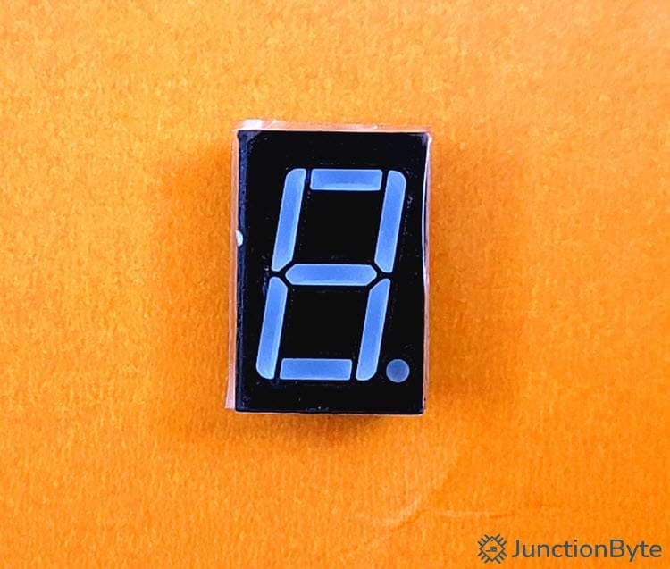
In addition to these seven segments, some displays come with an additional LED that acts as a decimal point.
Seven segment displays appear in many everyday electronic devices such as digital clocks, counters, calculators, basic digital meters, etc. Even in household space, appliances like microwaves and washing machines use seven segment displays for setting timers and viewing operational statuses.
Components and Structure of a 7-Segment Display
A seven segment display consists of seven rectangular LED segments arranged to form the number eight. Each segment is labelled ‘a’ through ‘g,’ starting from the top segment and moving clockwise. The eighth LED, labeled ‘dp,’ is the decimal point.
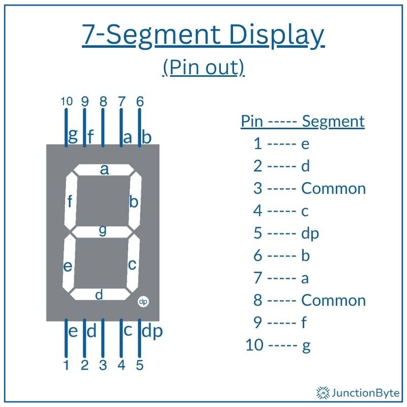
Each segment has two pins: one connected to a common terminal and the other to a dedicated control line. Depending on the type of Seven Segment Display, the common terminal connects either to ground or to a positive voltage. When current passes through two corresponding pins, the LED behind the segment turns on and the segment lights up.
Depending on the semiconductor material used, the LEDs in the Seven Segment Display can produce red (most popular option due to their high visibility), blue, green, and white colors.
Types of Seven Segment LED Displays
7-Segment Displays are available as two main types: Common Cathode (CC) and Common Anode (CA).
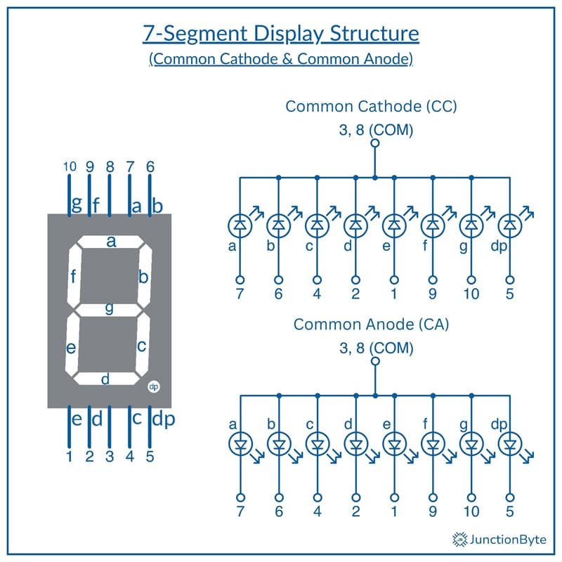
In Common Cathode (CC) displays, all cathodes of the LED segments connect to the common terminal, which acts as a common ground pin. Each segment’s anode connects to a separate control pin that typically connects to a microcontroller IO Pin and can activate a segment by supplying a positive voltage.
When a microcontroller outputs a HIGH signal to a segment pin, current flows from the positive supply, through the segment, and to the ground and this lights up the specific segment.
Coming to the Common Anode (CA) display, it connects all anodes of the LED segments to the common terminal, which is a common positive voltage pin. Each segment’s cathode acts as a separate control pin and we can activate a particular segment by grounding the corresponding pin.
In this case, the microcontroller pin must output a low signal to a segment pin so that current flows from the common anode, through the segment, and to ground. In this configuration, a LOW signal turns on a segment, while a HIGH signal turns it off.
Working Principle
From the previous discussion, you must be familiar with the internal construction of both the Common Cathode and Common Cathode type 7-Segment Displays and can guess how these segments form digits.
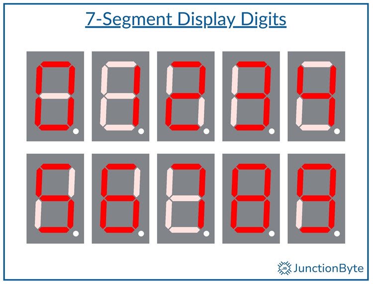
For example, to display the digit ‘0,’ we need to turn on all segments except ‘g.’ Similarly, to display ‘1,’ we need to activate only segments ‘b’ and ‘c.’ In addition to displaying numeric digits from 0 to 9, we can also show some letters and symbols on Seven Segment Displays. The most popular ones are upper case alphabets ‘A’ through ‘F’ for representing hexadecimal numbers.
In a Common Cathode configuration, the cathode (negative) of all the segments is connected to a common pin (GND – logic 0). To light up a segment, we have to apply a “HIGH” (logic 1) signal to that segment. The opposite is true for Common Anode configuration. Here, the anode (positive) of all the segments is connected to a common pin (Positive Voltage – logic 1). To light up a segment, we have to apply a “LOW” (logic 0) signal to that segment.
Truth Tables for Common Cathode and Common Anode
The following table shows which segments (a, b, c, d, e, f, g) should be ON (1) or OFF (0) for that character to appear on the display on a Common Cathode (CC) type 7-Segment Display.
| Digit | a | b | c | d | e | f | g |
| 0 | 1 | 1 | 1 | 1 | 1 | 1 | 0 |
| 1 | 0 | 1 | 1 | 0 | 0 | 0 | 0 |
| 2 | 1 | 1 | 0 | 1 | 1 | 0 | 1 |
| 3 | 1 | 1 | 1 | 1 | 0 | 0 | 1 |
| 4 | 0 | 1 | 1 | 0 | 0 | 1 | 1 |
| 5 | 1 | 0 | 1 | 1 | 0 | 1 | 1 |
| 6 | 1 | 0 | 1 | 1 | 1 | 1 | 1 |
| 7 | 1 | 1 | 1 | 0 | 0 | 0 | 0 |
| 8 | 1 | 1 | 1 | 1 | 1 | 1 | 1 |
| 9 | 1 | 1 | 1 | 1 | 0 | 1 | 1 |
You can make a similar truth table for Common Anode (CA) type Seven Segment Display by just inverting the values.
| Digit | a | b | c | d | e | f | g |
| 0 | 0 | 0 | 0 | 0 | 0 | 0 | 1 |
| 1 | 1 | 0 | 0 | 1 | 1 | 1 | 1 |
| 2 | 0 | 0 | 1 | 0 | 0 | 1 | 0 |
| 3 | 0 | 0 | 0 | 0 | 1 | 1 | 0 |
| 4 | 1 | 0 | 0 | 1 | 1 | 0 | 0 |
| 5 | 0 | 1 | 0 | 0 | 1 | 0 | 0 |
| 6 | 0 | 1 | 0 | 0 | 0 | 0 | 0 |
| 7 | 0 | 0 | 0 | 1 | 1 | 1 | 1 |
| 8 | 0 | 0 | 0 | 0 | 0 | 0 | 0 |
| 9 | 0 | 0 | 0 | 0 | 1 | 0 | 0 |
In these tables, the value of ‘1’ means the segment is given logic 1 (HIGH) and ‘0’ means the segment is given logic 0 (LOW).
Hardware Requirements to Interface a 7-Segment Display with an 8051 Microcontroller
Components Needed
- 8051 Microcontroller Board (AT89S52)
- Common Cathode 7-Segment Display
- Current-limiting Resistors (one 220Ω resistor per segment)
- Breadboard and Jumper Wires
- Reliable 5V Power Supply or USB Cable to Connect to a Computer
Circuit Diagram
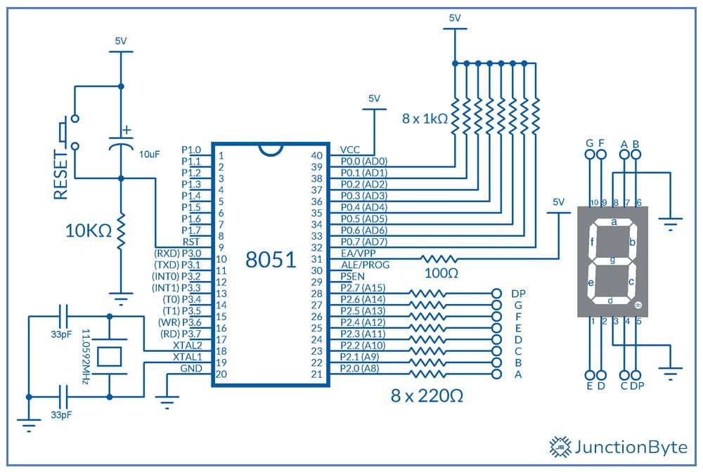
Connections Overview
Connect the Common Cathode Pins of the Seven Segment Display to the ground rail (GND – 0V). Next, connect each segment pin to a separate digital output pin on the 8051 microcontroller.
You can assign these connections logically to simplify the programming. For example, connect segment ‘a’ to P2.0, segment ‘b’ to P2.1, and so on until segment ‘g’ connects to P2.6. If the display has a decimal point, connect it to P2.7.
- Segment ‘a’ → P2.0
- Segment ‘b’ → P2.1
- Segment ‘c’ → P2.2
- Segment ‘d’ → P2.3
- Segment ‘e’ → P2.4
- Segment ‘f’ → P2.5
- Segment ‘g’ → P02.6
- Decimal Point ‘dp’ (optional) → P2.7
Don’t forget to connect a current-limiting resistor between each microcontroller pin and the corresponding segment pin. This resistor controls the current flowing through the segment LED and prevents it from burning out.
For a 5V supply, if we use 220Ω resistors, the current will be limited to approximately 15mA per segment.
Example Code for Interfacing 7-Segment Display with 8051 Microcontroller
Here is a sample code that displays digits ‘0’ through ‘9’ on a Common Cathode type 7-Segment Display. It will cycle through all the digits and repeat the process forever.
#include <reg52.h>

/* Define the Port to which the Segment Pins are Connected */
#define SEGMENT_PORT P2

unsigned char digits[10] = {
  0x3F, /* 0 */
  0x06, /* 1 */
  0x5B, /* 2 */
  0x4F, /* 3 */
  0x66, /* 4 */
  0x6D, /* 5 */
  0x7D, /* 6 */
  0x07, /* 7 */
  0x7F, /* 8 */
  0x6F /* 9 */
};

/* Function Prototypes */
/* Delay Function - to generate a small delay */
void delay(unsigned int ms);
/* Display Function - Displays the Digits */
void displayDigit(unsigned char num);

/* Main Function */
void main()
{
  unsigned char i = 0;
  SEGMENT_PORT = 0xFF; /* Set Port 0 as Output */
  while (1)
  {
    for (i = 0; i < 10; i++)
    {
      displayDigit(i);
      delay(500);
    }
  }
}

/* Display Functions */
void displayDigit(unsigned char num)
{
  if (num < 10)
  {
    SEGMENT_PORT = digits[num];
  }
}

/* Delay Function */
void delay(unsigned int ms)
{
  unsigned int i, j;
  for (i = 0; i < ms; i++)
  {
    for (j = 0; j < 1275; j++);
  }
}
Working (Explanation of Each Section)
To simplify digit display, we are using an array or lookup table to map the digits (0 – 9) to corresponding segment patterns. In a Common Cathode display, setting a pin HIGH lights up the segment, while setting it LOW turns the segment off.
The following is an array with pre-calculated binary values for each digit.
unsigned char digits[10] = {
  0x3F, /* 0 */
  0x06, /* 1 */
  0x5B, /* 2 */
  0x4F, /* 3 */
  0x66, /* 4 */
  0x6D, /* 5 */
  0x7D, /* 6 */
  0x07, /* 7 */
  0x7F, /* 8 */
  0x6F /* 9 */
};
For example, 0x3F lights up segments a, b, c, d, e, and f to form the digit ‘0.’
In the ‘main’ function, we are setting the Port 2 as an output by assigning 0xFF to P2. Then, we are cycling through digits 0 to 9 with a 500 ms delay between each by calling the ‘displayDigit()’ and ‘delay()’ functions.
How to Interface a 4-Digit 7-Segment Display with 8051 Microcontroller?
A Brief Note on 4-Digit 7-Segment Display
The limitation of a 7-Segment Display is that it can display only one digit. If you want to display more than one digit, you need to add multiple Seven Segment Displays to the circuit.
However, if you connect individual 7-Segment Displays to a microcontroller, you will need 8 Pins per display. For example, you will need 32 pins of the microcontroller (7 Segment Pins and 1 Decimal per display). This is practically not feasible.
A simple solution to this is to Multiplex the displays. This way, you will need 8 pins for 8 segments (including decimal) and additionally one pin per display for the common terminals. This method reduces the number of pins required to control the display. For example, instead of needing 32 pins for four digits, multiplexing allows control with just 12 pins.
You can manually implement the multiplexing logic but we use 4-Digit 7-Segment Display Modules that are readily available in the market. Here’s a typical 4-Digit 7-Segment Display Module.
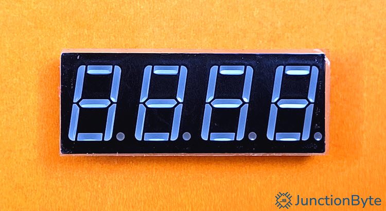
Like individual Seven Segment Displays, even the 4-Digit 7-Segment Display Modules are available as Common Cathode (CC) or Common Anode (CA). This particular model I have is of CC type.
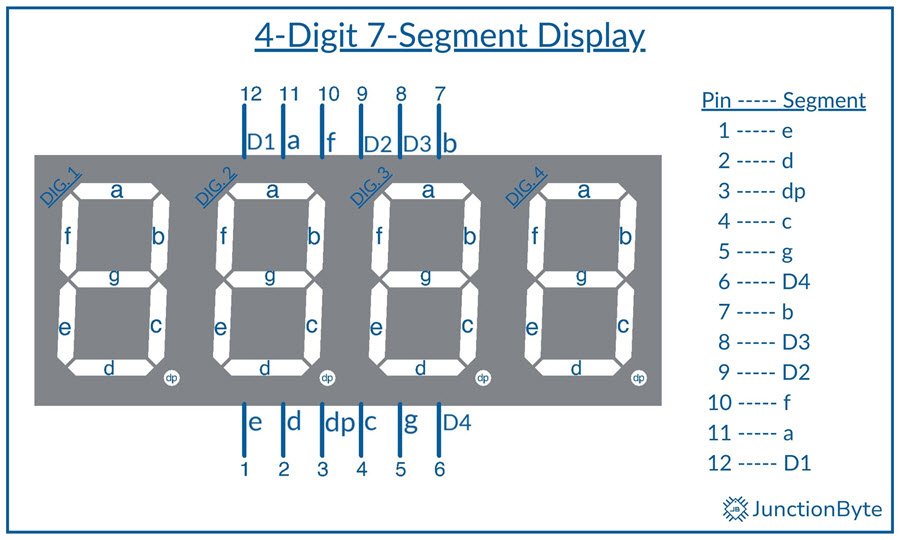
The following image shows the 4-Digit 7-Segment Display Module Pinout.
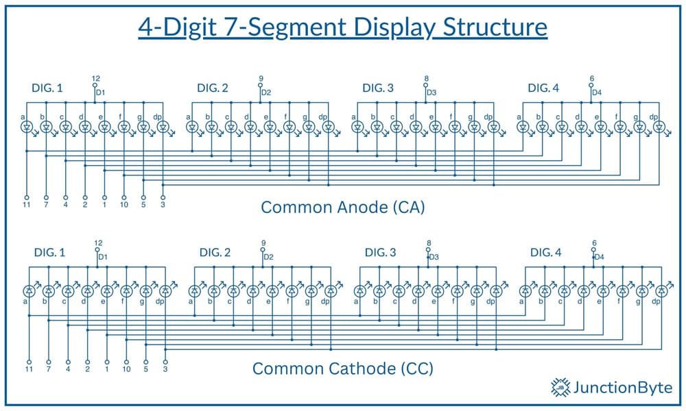
If you are interested in understanding the working, here’s a look at the internal logic of a 4-Digit 7-Segment Display (both CC and CA).
Circuit Diagram for Connecting 4-Digit 7-Segment Display with 8051 Microcontroller
As I mentioned before, we need 12 Pins of the microcontroller to interface a 4-Digit 7-Segment Display. We can connect the Segment Pins of the display (7 Segments + 1 Decimal) to any Port of the 8051 Microcontroller (let us say Port 0). This of course includes individual current limiting resistors for all the segment pins.
Next, instead of connecting the Digit Selection Pins directly to the Microcontroller, we can use transistors (simple NPN transistors such as 2N2222A) to control the digits. Here is what the connection looks like:
- The base of each NPN transistor connects to a microcontroller pin (e.g., P2.0, P2.1, P2.2, P2.3). We have to add current-limiting resistors between the microcontroller pins and the base of the transistors.
- Next, the collector of each NPN transistor connects to the common terminal (cathode) of the corresponding digit (D1, D2, D3, D4).
- Last but not least, the emitter of each NPN transistor connects to ground.
Code for Interfacing a 4-Digit 7-Segment Display with 8051 Microcontroller
#include <reg52.h>

/* Define Port for Segment Pins */
#define SEGMENT_PORT P2

/* Define Segment Codes for Digits 0-9 (Common Cathode) */
unsigned char segmentCode[] = {
0x3F, /* 0 */
0x06, /* 1 */
0x5B, /* 2 */
0x4F, /* 3 */
0x66, /* 4 */
0x6D, /* 5 */
0x7D, /* 6 */
0x07, /* 7 */
0x7F, /* 8 */
0x6F /* 9 */
};

/* Define Digit Selection Pins (Connected to NPN Transistor Bases) */
sbit D1 = P0^0; /* Thousands Place */
sbit D2 = P0^1; /* Hundreds Place */
sbit D3 = P0^2; /* Tens Place */
sbit D4 = P0^3; /* Units Place */

/* Function to delay for a specific time (using Timer 0)
void delay_ms(unsigned int ms)
{
  unsigned int i, j;
  for (i = 0; i < ms; i++)
  {
    for (j = 0; j < 123; j++); /* Approximate 1ms delay for 11.0592 MHz */
  }
}

/* Function to Display a 4-digit Number on the 7-Segment Display */
void display_number(unsigned int num)
{
  unsigned char digits[4];
  unsigned char i;
  unsigned char display_digits = 4; /* Default: Display all 4 Digits */

  /* Extract Individual Digits */
  digits[0] = num / 1000;   	// Thousands place
  digits[1] = (num / 100) % 10; // Hundreds place
  digits[2] = (num / 10) % 10;  // Tens place
  digits[3] = num % 10;     	// Units place

  /* Determine which digits to display based on the value of num */
  if (num < 10)
  {
    display_digits = 1; /* Only display the last digit (units place) */
  }
  else if (num < 100)
  {
    display_digits = 2; /* Display last two digits (tens and units place) */
  }
  else if (num < 1000)
  {
    display_digits = 3; /* Display last three digits (hundreds, tens, and units place) */
  }

  /* Display each digit for a short time (multiplexing) */

  for (i = 0; i < display_digits; i++)
  {
    /* Send segment code to Port 1 */
    SEGMENT_PORT = segment_code[digits[4 - display_digits + i]];

    /* Select the corresponding digit by turning on the NPN transistor */
    switch (4 - display_digits + i)
    {
      case 0: D1 = 1; D2 = 0; D3 = 0; D4 = 0; break; /* Turn on D1 (Thousands place) */
      case 1: D1 = 0; D2 = 1; D3 = 0; D4 = 0; break; /* Turn on D2 (Hundreds place) */
      case 2: D1 = 0; D2 = 0; D3 = 1; D4 = 0; break; /* Turn on D3 (Tens place) */
      case 3: D1 = 0; D2 = 0; D3 = 0; D4 = 1; break; /* Turn on D4 (Units place) */
    }

    delay_ms(5); // Display each digit for 5ms

    /* Turn off all digits after displaying */
    D1 = 0;
    D2 = 0;
    D3 = 0;
    D4 = 0;
  }
}

void main()
{
  unsigned int count = 0;
  while (1)
  {
    /* Display the current number */
    display_number(count);

    /* Increment the count */
    count++;
    if (count > 9999)
    {
    count = 0; /* Reset to 0 after 9999 */
    }

    /* Delay for 1 second */
    delay_ms(1000);
  }
}
Conclusion
A complete beginner’s guide on how to interface a 7-Segment Display with an 8051 Microcontroller. We saw the basics of Seven Segment Display, types (Common Cathode and Common Anode), and the steps you need to follow to interface a 7-Segment Display with 8051 Microcontroller. After that, we saw an example code to display digits on a Common Cathode type 7-Segment Display using 8051 Microcontroller.
Additionally, we also learned the 4-Digit 7-Segment Display and how to connect one to an 8051 Microcontroller.