Many embedded systems need accurate timekeeping for various applications, such as digital clocks, data loggers, attendance systems, and event schedulers. Real Time Clocks (RTCs) help in maintaining accurate time and date information. Most modern microcontrollers nowadays come with built-in RTC hardware. However, basic microcontrollers such as the 8051, Arduino, etc. don’t have the RTC hardware. So, how can we add this timekeeping functionality? This is where the dedicated RTC ICs such as DS1307 and DS3231 come into play. In this guide, I will show you how to interface RTC with an 8051 microcontroller.
First, we will learn some basics of Real Time Clocks (RTCs), the DS3231 RTC Module, and how it communicates with microcontrollers. Then, we will see how to write demo C programs to interface DS3231 RTC Module with 8051 Microcontroller.
Basics of Real-Time Clocks (RTCs)
A Real-Time Clock (RTC) is an integrated circuit that keeps track of the current time and date. It tracks seconds, minutes, hours, days, months, and years, including leap years.
Unlike general-purpose timers in microcontrollers, RTCs run continuously and maintain time consistently, even when the primary system loses power. RTC modules generally include a battery backup feature, which allows them to work even when the main system is turned off.
RTCs operate independently with their dedicated quartz crystal oscillator that provides a stable time base. The oscillator generates precise pulses, which the RTC divides to track seconds. Manufacturers calibrate these crystals to minimize time drift, usually within a few seconds per month. Some advanced RTCs have a temperature compensation feature to have better accuracy.
Most RTC modules communicate with microcontrollers through serial interfaces like I2C or SPI. The I2C interface, commonly used in modules like the DS1307 and DS3231, requires only two communication lines (SCL and SDA).
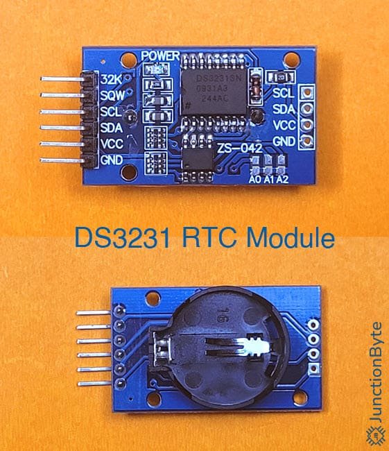
Overview of DS3231 RTC Module
The DS3231 is one of the most popular RTC modulus in the DIY and hobbyist community. It is developed by Maxim Integrated, which is now a part of Analog Devices.
An interesting feature of the DS3231 RTC module is its built-in Temperature-Compensated Crystal Oscillator (TCXO). This oscillator helps in maintaining accurate time regardless of temperature fluctuations.
Standard crystal oscillators drift over time because temperature changes affect their frequency. To counter this, the DS3231 measures its internal temperature and adjusts the oscillator’s frequency accordingly. This adjustment keeps the timekeeping precise, even in extreme environmental conditions.
The DS3231 maintains accuracy across a temperature range from -40°C to +85°C. The TCXO in the DS3231 has an accuracy of ±2 parts per million (ppm) for a temperature range of 0°C to +40°C. This translates to a maximum drift of about one minute per year.
If you compare with the other most popular RTC, the DS1307, they drift by about one minute per month.
For communication, the DS3231 uses the I2C protocol. From the previous guide, we know that the 8051 Microcontroller doesn’t have built-in I2C hardware. So, I will be using software bit-banging to generate the necessary data and clock signals. For more information, take a look at the ‘8051 Microcontroller I2C’ guide.
Built-in Alarm Functions and Square-Wave Output
The DS3231 has two programmable alarms that trigger events at specific times or dates. These alarms operate independently and we can configure them for daily, weekly, or one-time events.
In addition to the alarm functions, the DS3231 also has a square-wave output that can generate clock pulses at programmable frequencies. We can select between the following frequencies: 1 Hz, 1.024 kHz, 4.096 kHz, or 8.192 kHz.
The square wave output can be useful for generating periodic interrupts to microcontrollers.
Pin Configuration and Description
The DS3231 module has six pins: VCC, GND, SDA, SCL, SQW, and 32K.
- VCC: Powers the module with a supply voltage range of 2.3V to 5.5V.
- GND: Connects to the system ground (0V).
- SDA (Serial Data): Transmits data between the microcontroller and the DS3231 using the I2C protocol.
- SCL (Serial Clock): Carries the clock signal from the microcontroller.
- SQW (Square Wave Output): Outputs programmable square wave signals.
- 32K (32.768 kHz Output): Provides a fixed 32.768 kHz clock signal.
Internal Register Map of DS3231
The DS3231 has a bunch of internal registers that store time, date, alarm settings, and configuration data. These registers, accessed through the I2C interface, control the module’s functions.
Here are some of the key registers of the DS3231 RTC:
- 0x00H – 0x06H (Time and Date Registers): Stores the seconds, minutes, hours, day, date, month, and year data. The module uses Binary-Coded Decimal (BCD) format.
- 0x07H – 0x0DH (Alarm Registers): Configures Alarm 1 and Alarm 2 settings for specific times or date events.
- 0x0EH (Control Register): Manages the square-wave output, alarm interrupts, and oscillator settings.
- 0x0FH (Status Register): Contains flags for alarm triggers, oscillator status, and temperature conversion.
- 0x11H and 0x12H (Temperature Registers): Holds the current temperature data with a resolution of 0.25°C (MSB and LSB).
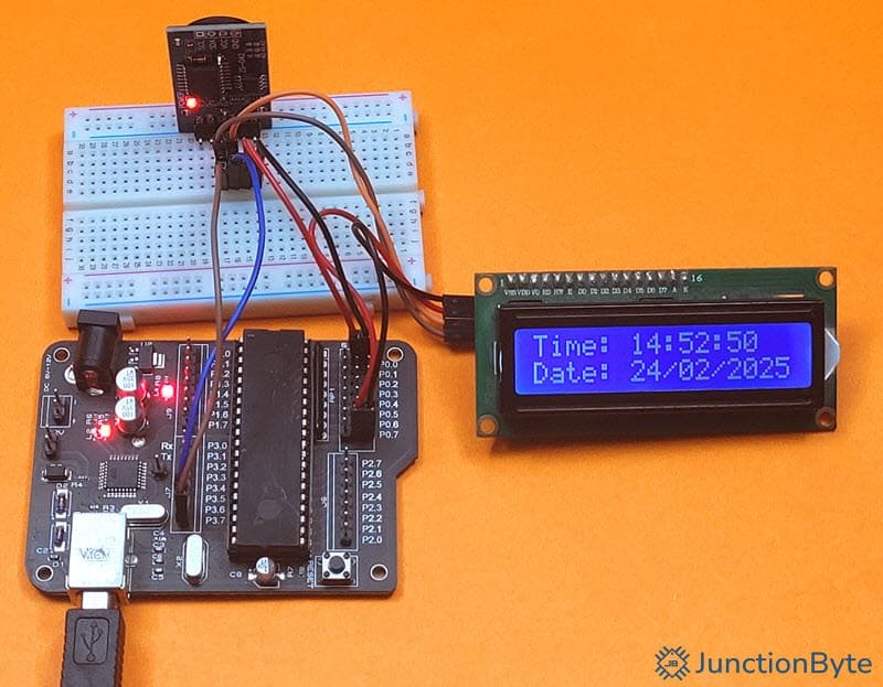
Hardware Requirements and Circuit Diagram
Let us build a simple system that connects the DS3231 RTC Module with the 8051 Microcontroller and displays the data and time information on an LCD. Since the communication between the 8051 and DS3231 is I2C, we can leverage this by adding the PCF8574 I2C LCD in the mix.
This way, we only need two wires from the 8051 Microcontroller to interface with the RTC as well as the display.
Components Needed
- DS3231 RTC Module
- 8051 Microcontroller (I will be using AT89S52 for demonstration)
- PCF8574 I2C LCD Module (16×2 or 20×4)
- Connecting Wires and Power Supply
Circuit Diagram
Here’s the circuit diagram for interfacing DS3231 RTC Module with an 8051 Microcontroller. The circuit diagram also shows the connections for the PCF8574 I2C LCD.
Code for Interfacing DS3231 RTC with 8051 Microcontroller
Let us now write the C program for interfacing the DS3231 RTC with the 8051 microcontroller.
I2C Driver
First, all the communication between the 8051 Microcontroller and the DS3231 RTC Module and PCF8574 LCD happens over I2C. So, we need to import our I2C Driver that we implemented in the previous 8051 Microcontroller I2C guide.
#ifndef AT89S52_I2C_H_
#define AT89S52_I2C_H_

/* Include the Main 8051 Header File */
#include <reg52.h>
/* This header is necessary for using NOP */
#include <intrins.h>

/* Define two GPIO Pins, one for SDA and one for SCL */
sbit SDA = P3^6; /* Define SDA Pin */
sbit SCL = P3^7;  /* Define SCL Pin */

/* I2C Function Prototypes */
bit I2C_Start(void);
bit I2C_Stop(void);
bit I2C_Write(unsigned char datax);
unsigned char I2C_Read(unsigned char ack);

/* I2C Function Definitions */

/* The I2C_Start function creates the START condition.
 * Pull SDA LOW while SCL is HIGH. */
bit I2C_Start(void)
{
  SCL = 0;
  SDA = 1;
  _nop_ ();
  SCL = 1;
  _nop_ ();
  SDA = 0;
  _nop_ ();
  SCL = 0;
  return 1;
}

/* The I2C_Stop function creates the STOP condition.
 * Pull SDA HIGH while SCL is HIGH. */
bit I2C_Stop(void)
{
  SCL = 0;
  _nop_ ();
  SDA = 0;
  _nop_ ();
  SCL = 1;
  _nop_ ();
  SDA = 1;
  return 1;
}

/* The I2C_Write Function Transmits one byte (8 bits) over the I2C bus.
 * The MSB (Most Significant Bit) is sent first.
 * After all 8 bits are sent,
 * SDA is released to receive an acknowledgment (ACK)
 * from the slave. */

bit I2C_Write(unsigned char datax)
{
  unsigned char i;
  for (i = 0; i < 8; i++)
  {
    SDA = datax & 0x80;
    _nop_ ();
    SCL = 1;
    _nop_ ();
    SCL = 0;
    datax = datax << 1;
  }
  SDA = 1;
  _nop_ ();
  SCL = 1;
  _nop_ ();
  if (SDA == 0)
  {
    SCL = 0;
    _nop_ ();
    return 1;
  }
  SCL = 0;
  _nop_ ();
  return 0;
}

/* The I2C_Read Function Reads 8 bits from the I2C slave.
 * Stores received bits in datax.
 * ACK (1) is sent if more data is expected.
 * Otherwise NACK (0) is sent. */

unsigned char I2C_Read(unsigned char ack)
{
  unsigned char i, datax = 0;
  SDA = 1;  /* Release SDA for reading */
  for (i = 0; i < 8; i++)
  {
    SCL = 1; /* Generate clock pulse */
    datax = (datax << 1) | SDA; /* Read the bit */
    SCL = 0; /* Bring SCL low */
  }

  if (ack)
  {
    SDA = 0; /* Pull SDA LOW to Send ACK */
    _nop_ ();
    SCL = 1; /* Generate clock for ACK */
    _nop_ (); /* Wait for Some time */
    SCL = 0;  /* Bring SCL low */
    _nop_ ();
    SDA = 1; /* Pull SDA back to HIGH */
  }
  else
  {
    SDA = 1; /* Send NACK */
    _nop_ ();
    SCL = 1; /* Generate clock for NACK */
    _nop_ (); /* Wait for Some time */
    SCL = 0;  /* Bring SCL LOW */
    _nop_ (); /* Wait for Some time */
    SCL = 1;
  }
  return datax; // Return the data read
}

#endif
PCF8574 I2C LCD Driver
Next, to display the time and date information, we are using the PCF8574 I2C LCD. I already made a detailed guide on ‘How to Interface PCF8574 I2C LCD with 8051 Microcontroller.’ I wrote a driver specifically for the PCF8574 I2C LCD using the previous I2C Driver. We can use that here. So, I will import the PCF8574 I2C LCD driver as well.
#ifndef AT89S52_I2C_LCD_H_
#define AT89S52_I2C_LCD_H_

#include "at89s52_i2c.h"
#define LCD_ADDR (0x3F << 1)  /* PCF8574 I2C address for LCD */
#define BACKLIGHT 0x08   /* P3 controls the backlight (1 = ON, 0 = OFF)*/

/* Function Prototypes */
void I2C_LCD_Delay(unsigned int ms);
void I2C_LCD_SendCommand(unsigned char cmd);
void I2C_LCD_SendData(unsigned char datax);
void I2C_LCD_Init(void);
void I2C_LCD_Clear(void);
void I2C_LCD_SetCursor(unsigned char row, unsigned char col);
void I2C_LCD_WriteChar(char ch);
void I2C_LCD_WriteString(char *str);

void I2C_LCD_SendCommand(unsigned char cmd)
{
  /* Send High Nibble First */
  I2C_Start();
  I2C_Write(LCD_ADDR);   /* Send device address with write Bit */
  I2C_Write((cmd & 0xF0) | BACKLIGHT);  /* Send high nibble with backlight ON */
  I2C_Stop();

  I2C_LCD_Delay(1);

  I2C_Start();
  I2C_Write(LCD_ADDR);   /* Send device address with write Bit */
  /* Toggle Enable HIGH and LOW */
  I2C_Write((cmd & 0xF0) | BACKLIGHT | 0x04);  /* EN = 1 */
  I2C_Stop();

  I2C_LCD_Delay(1);

  I2C_Start();
  I2C_Write(LCD_ADDR);   /* Send device address with write Bit */
  I2C_Write((cmd & 0xF0) | BACKLIGHT);         /* EN = 0 */
  I2C_Stop();

  I2C_LCD_Delay(1);

  /* Send Low Nibble Next */
  I2C_Start();
  I2C_Write(LCD_ADDR);   /* Send device address with write Bit */
  I2C_Write(((cmd << 4) & 0xF0) | BACKLIGHT);  /* Send low nibble with backlight ON */
  I2C_Stop();

  I2C_LCD_Delay(1);

  I2C_Start();
  I2C_Write(LCD_ADDR);   /* Send device address with write Bit */
  /* Toggle Enable HIGH and LOW */
  I2C_Write(((cmd << 4) & 0xF0) | BACKLIGHT | 0x04);  /* EN = 1 */
  I2C_Stop();

  I2C_LCD_Delay(1);

  I2C_Start();
  I2C_Write(LCD_ADDR);   /* Send device address with write Bit */
  I2C_Write(((cmd << 4) & 0xF0) | BACKLIGHT);         /* EN = 0 */
  I2C_Stop();

  I2C_LCD_Delay(1);
}

void I2C_LCD_SendData(unsigned char datax)
{
  /* Send High Nibble First */
  I2C_Start();
  I2C_Write(LCD_ADDR);   /* Send device address with write Bit */
  /* Send high nibble with RS=1 and backlight ON */
  I2C_Write((datax & 0xF0) | BACKLIGHT | 0x01);
  I2C_Stop();

  /* Toggle Enable HIGH and LOW */
  I2C_Start();
  I2C_Write(LCD_ADDR);   /* Send device address with write Bit */
  I2C_Write((datax & 0xF0) | BACKLIGHT | 0x05);  /* EN = 1, RS = 1 */
  I2C_Stop();

  I2C_LCD_Delay(1);

  I2C_Start();
  I2C_Write(LCD_ADDR);   /* Send device address with write Bit */
  I2C_Write((datax & 0xF0) | BACKLIGHT | 0x01);  //* EN = 0, RS = 1 */
  I2C_Stop();

  I2C_LCD_Delay(1);

  /* Send Low Nibble Next */
  I2C_Start();
  I2C_Write(LCD_ADDR);   /* Send device address with write Bit */
  /* Send low nibble with RS=1 and backlight ON */
  I2C_Write(((datax << 4) & 0xF0) | BACKLIGHT | 0x01);
  I2C_Stop();

  I2C_LCD_Delay(1);

  I2C_Start();
  I2C_Write(LCD_ADDR);   /* Send device address with write Bit */
  /* Toggle Enable HIGH and LOW */
  I2C_Write(((datax << 4) & 0xF0) | BACKLIGHT | 0x05);  /* EN = 1, RS = 1 */
  I2C_Stop();

  I2C_LCD_Delay(1);

  I2C_Start();
  I2C_Write(LCD_ADDR);   /* Send device address with write Bit */
  I2C_Write(((datax << 4) & 0xF0) | BACKLIGHT | 0x01);  /* EN = 0, RS = 1 */
  I2C_Stop();

  I2C_LCD_Delay(2);
}

void I2C_LCD_Init(void)
{
  /* Initialize the LCD in 4-Bit Mode */
  I2C_LCD_Delay(20);  /* Wait for LCD to power up */
  I2C_LCD_SendCommand(0x28);   /* 4-bit interface, 2 lines, 5x7 font */
  I2C_LCD_SendCommand(0x0C);   /* Display ON, Cursor OFF */
  I2C_LCD_SendCommand(0x06);   /* Entry mode: Increment, No shift */
  I2C_LCD_SendCommand(0x01);   /* Clear display */
  I2C_LCD_Delay(2);  /* Wait for the command to be executed */
}

void I2C_LCD_Clear(void)
{
  I2C_LCD_SendCommand(0x01);  /* Clear display */
  I2C_LCD_Delay(2);  /* Wait for the command to be executed */
}

void I2C_LCD_SetCursor(unsigned char row, unsigned char col)
{
  unsigned char address;
  if (row == 0)
  {
    address = 0x80 + col;  /* First row address */
  }
  else
  {
    address = 0xC0 + col;  /* Second row address */
  }
  I2C_LCD_SendCommand(address);  /* Set cursor to specific location */
}

void I2C_LCD_WriteChar(char ch)
{
  I2C_LCD_SendData(ch);  /* Send Data (character) to LCD */
}

void I2C_LCD_WriteString(char *str)
{
  while (*str)
  {
    I2C_LCD_WriteChar(*str);
    str++;
  }
}

void I2C_LCD_Delay(unsigned int ms)
{
  unsigned int i, j;
  for (i = 0; i < ms; i++)
  {
    for (j = 0; j < 123; j++);
  }
}
#endif
DS3231 RTC Driver
#ifndef AT89S52_DS3231_H_
#define AT89S52_DS3231_H_

#include "at89s52_i2c.h"

/* Define DS3231 I2C Address */
#define DS3231_ADDR 0x68   /* 7-Bit Address for DS3231 */

/* Define DS3231 Registers */
#define REG_SEC 0x00
#define REG_MIN 0x01
#define REG_HOUR 0x02
#define REG_DAY 0x03
#define REG_DATE 0x04
#define REG_MONTH 0x05
#define REG_YEAR 0x06
#define REG_CTRL 0x0E

/* DS3231 Function Prototypes */
void DS3231_Init(void);

void DS3231_SetTime(unsigned char hour, unsigned char min, unsigned char sec);
void DS3231_SetDate(unsigned char date, unsigned char month, unsigned char year);

void DS3231_GetTime(unsigned char *timeArray);
void DS3231_GetDate(unsigned char *dateArray);

unsigned char BCD_to_Decimal(unsigned char bcd);
unsigned char Decimal_to_BCD(unsigned char dec);

/* Function to Initialize the DS3231 RTC.
 * We are essentially enabling the Internal Oscillator */
void DS3231_Init(void)
{
  I2C_Start();
  I2C_Write(DS3231_ADDR << 1);  /* Write Mode */
  I2C_Write(REG_CTRL);          /* Control Register Address */
  I2C_Stop();

  I2C_Start();
  I2C_Write(DS3231_ADDR << 1);  /* Write Mode */
  I2C_Write(0x00);              /* Enable Oscillator */
  I2C_Stop();
}

void DS3231_SetTime(unsigned char sec, unsigned char min, unsigned char hour)
{
  I2C_Start();
  I2C_Write(DS3231_ADDR << 1);    /* Write Mode */
  I2C_Write(REG_SEC);             /* Select the Seconds Register */

  I2C_Write(Decimal_to_BCD(sec)); /* Set Seconds */
  I2C_Write(Decimal_to_BCD(min)); /* Set Minutes */
  I2C_Write(Decimal_to_BCD(hour));/* Set Hours */

  I2C_Stop();
}

void DS3231_SetDate(unsigned char date, unsigned char month, unsigned char year)
{
  I2C_Start();
  I2C_Write(DS3231_ADDR << 1);      /* Write Mode */
  I2C_Write(REG_DATE);              /* Select the Date Register */

  I2C_Write(Decimal_to_BCD(date));  /* Set Date */
  I2C_Write(Decimal_to_BCD(month)); /* Set Month */
  I2C_Write(Decimal_to_BCD(year));  /* Set Year */
  I2C_Stop();
}

void DS3231_GetTime(unsigned char *timeArray)
{
  I2C_Start();
  I2C_Write(DS3231_ADDR << 1);       /* Write Mode */
  I2C_Write(REG_SEC);                /* Start at the Seconds Register */
  I2C_Stop();

  I2C_Start();
  I2C_Write((DS3231_ADDR << 1) | 1); /* Read Mode */

  timeArray[2] = I2C_Read(1);  /* Seconds */
  timeArray[1] = I2C_Read(1);  /* Minutes */
  timeArray[0] = I2C_Read(0);  /* Hours */

  I2C_Stop();
}

void DS3231_GetDate(unsigned char *dateArray)
{
  I2C_Start();
  I2C_Write(DS3231_ADDR << 1);       /* Write Mode */
  I2C_Write(REG_DATE);               /* Start at the Date Register */
  I2C_Stop();

  I2C_Start();
  I2C_Write((DS3231_ADDR << 1) | 1); /* Read Mode */

  dateArray[0] = I2C_Read(1);  /* Date */
  dateArray[1] = I2C_Read(1);  /* Month */
  dateArray[2] = I2C_Read(0);  /* Year */

	I2C_Stop();
}

unsigned char BCD_to_Decimal(unsigned char bcd)
{
  return ((bcd >> 4) * 10) + (bcd & 0x0F);
}

unsigned char Decimal_to_BCD(unsigned char dec)
{
  return ((dec / 10) << 4) | (dec % 10);
}

#endif
Example C Program for DS3231 RTC Interface
#include <reg52.h>
#include <stdio.h>
#include "at89s52_i2c.h"
#include "at89s52_i2c_lcd.h"
#include "at89s52_ds3231.h"

void main (void)
{
  unsigned char timeArray[3];
  unsigned char dateArray[3];
  char buffer[16];

  I2C_LCD_Init();
  I2C_LCD_Clear();

  DS3231_Init();

  /* Set Initial Time and Date (example: 14:30:45, 28/02/25)*/
  DS3231_SetTime(14, 30, 45);
  DS3231_SetDate(28, 2, 25);

  while(1)
  {
    DS3231_GetTime(timeArray ); /* Get Time */
    DS3231_GetDate(dateArray); /* Get Date */

    /* Display Time */
    I2C_LCD_SetCursor(0, 0);
    sprintf(buffer, "Time: %02X:%02X:%02X", (unsigned int)timeArray[0], (unsigned int)timeArray[1], (unsigned int)timeArray[2]);
    I2C_LCD_WriteString(buffer);

    /* Display Date */
    I2C_LCD_SetCursor(1, 0);
    sprintf(buffer, "Date: %02X/%02X/20%02X", (unsigned int)dateArray[0], (unsigned int)dateArray[1], (unsigned int)dateArray[2]);
    I2C_LCD_WriteString(buffer);
  }
}
Conclusion
A useful guide on interfacing DS3231 RTC Module with 8051 Microcontroller. I implemented only the basic ‘get’ and ‘set’ function for time and date. However, we can add more functionality to the driver with alarms, square wave output, and many more.