The 8051 Microcontroller is a very simple architecture. This 8-bit microcontroller gained popularity because of its efficient instruction set and ease of programming. When it comes to built-in peripherals though, things are as basic as it can get. You have a couple of Timers and a Serial Port (UART). There is no I2C, SPI, or other communication hardware, there are no ADC and DAC blocks, and definitely no DMA (or other advanced features). However, the 8051 Microcontroller (or rather the MCS-51 Architecture) did have one of the important features of any microcontroller: Interrupts. With interrupts, microcontrollers have an efficient way to handle high-priority real-time events. In this guide, let us take a closer look at 8051 Microcontroller Interrupts.
We have been using the interrupts feature of the 8051 Microcontroller in the previous guides. For example, if you remember the 8051 Microcontroller PWM guide, we used the Timer Interrupt to generate a PWM signal.
I will first explain the importance of Interrupts in embedded systems. Then, we will look at different types of interrupts in an 8051 Microcontroller. I will also provide some example codes for you to understand all the 8051 Microcontroller Interrupts.
What are Interrupts?
In a typical embedded systems application, a microcontroller must handle multiple tasks efficiently. Some tasks need immediate processing, while others can wait. Interrupts provide a way for the microcontroller to respond quickly to urgent events without constant monitoring.
An interrupt is a signal that temporarily stops the normal execution of a program to perform a high-priority task. When an ‘Interrupt’ occurs, the microcontroller pauses the main program, executes a specific function, and then resumes normal operation.
In real-time applications, a microcontroller must react quickly to sensor inputs, communication requests, or timing events. Instead of waiting for an event, the processor continues executing other operations. When the event happens, it interrupts the microcontroller so that it has full attention of the processor only when necessary.
For example, a temperature monitoring system must alert users when the temperature exceeds a set limit. If the microcontroller keeps checking for the temperature every minute or so, it is wasting its precious resources and power. Using interrupts, the microcontroller can remain in a low-power state for most of the time. When the temperature sensor detects a rise in temperature, it interrupts the microcontroller, which then wakes up and alerts the user.
Polling vs. Interrupts
Microcontrollers can detect/handle events using two methods: polling and interrupts.
Polling is a process where the microcontroller to repeatedly check a specific condition or check for a change in status in a loop. This technique consumes processing power because it constantly executes instructions, even when no event occurs.
Interrupts, on the other hand, eliminates this unnecessary processing by allowing the microcontroller to wait in an idle state or execute other tasks. The processor responds only when an event triggers an interrupt signal.
Consider a button-controlled system. In polling, the microcontroller continuously checks the button’s status. This process consumes resources and power even when no press occurs. In an interrupt-driven approach, the microcontroller waits in a low-power state and responds only when the button triggers an event. This method allows microcontrollers to manage multiple tasks without wasting processing time and power.
How Interrupts Work?
An interrupt signal informs the microcontroller that an event requires immediate attention. This signal can originate from an external device, a timer overflow, or a communication module. Once the interrupt occurs, the microcontroller temporarily stops executing the main program and transfers control to a predefined routine. Here’s how the interrupt mechanism works:
First, the processor completes the current instruction to avoid corruption. Then, it saves key register values, such as the program counter and processor status in memory. Next, the processor jumps to a specific function know as the Interrupt Service Routine (ISR)., which is specific to that particular interrupt. The processor begins execution of the ISR.
Once the ISR completes its task, the processor restores the saved register values. It then resumes execution from the point where the interrupt occurred.
8051 Microcontroller Interrupts
The standard 8051 microcontroller supports five interrupt sources. These sources are: two external interrupts, two timer interrupts, and one serial communication interrupt.
- External Interrupt 0 (INT0) – Triggered by a signal on the external interrupt pin (P3.2)
- Timer Interrupt 0 (TF0) – Occurs when Timer 0 overflows
- External Interrupt 1 (INT1) – Triggered by an external signal on pin P3.3
- Timer Interrupt 1 (TF1) – Generated when Timer 1 overflows
- Serial Communication Interrupt (RI/TI) – Activated when data is received or transmitted
Before looking at these interrupts in detail, let us take a quick look at the different registers (SFRs) that are associated with interrupts in the 8051 Microcontroller.
8051 Microcontroller Interrupt SFRs
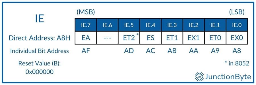
Interrupt Enable (IE) Register
The Interrupt Enable (IE) register consists of individual bits for enabling or disabling specific interrupts. If a bit is set to 1, the corresponding interrupt remains active. If cleared to 0, the microcontroller ignores the interrupt request.
| Symbol | Description | Notes |
| EA | Global Interrupt Enable/Disable Bit | EA=0, all Interrupts are disabled. EA=1, individual interrupts can be enabled/disabled |
| — | Reserved | |
| ET2 | Reserved in original 8051. Timer 2 Overflow Interrupt Enable Bit | ET2=0, Timer 2 Overflow Interrupt is Disabled. ET2=1, Timer 2 Overflow Interrupt is Enabled. |
| ES | Serial Port Interrupt Enable Bit | ES=0, Disable Serial Port Interrupt (TI or RI). ES=1, Enable Serial Port Interrupt (TI or RI). |
| ET1 | Timer 1 Overflow Interrupt Enable Bit | ET1=0, Timer 1 Overflow Interrupt is Disabled. ET1=1, Timer 1 Overflow Interrupt is Enabled. |
| EX1 | External Interrupt 1 Interrupt Enable Bit | EX1=0, Disable External Interrupt 1. EX1=1, Enable External Interrupt 1. |
| ET0 | Timer 0 Overflow Interrupt Enable Bit | ET0=0, Timer 0 Overflow Interrupt is Disabled. ET0=1, Timer 0 Overflow Interrupt is Enabled. |
| EX0 | External Interrupt 0 Interrupt Enable Bit | EX0=0, Disable External Interrupt 0. EX0=1, Enable External Interrupt 0. |
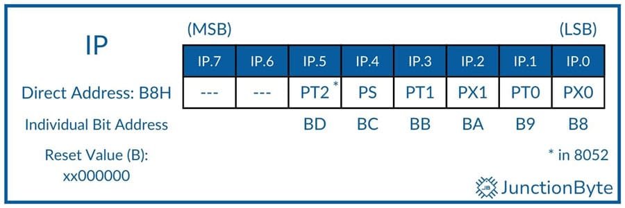
Interrupt Priority (IP) Register
The Interrupt Priority (IP) register determines which interrupt the microcontroller processes first when multiple requests occur simultaneously. Higher-priority interrupts preempt lower-priority ones.
| Symbol | Description |
| — | Reserved |
| — | Reserved |
| PT2 | Reserved in original 8051. Timer 2 Interrupt Priority Bit |
| PS | Serial Port Interrupt Priority Bit |
| PT1 | Timer 1 Interrupt Priority Bit |
| PX1 | External Interrupt 1 Interrupt Priority Bit |
| PT0 | Timer 0 Interrupt Priority Bit |
| PX0 | External Interrupt 0 Interrupt Priority Bit |
Setting a bit to 1 assigns high priority to the corresponding interrupt. Bits left at 0 remain as low priority. If two interrupts with the same priority trigger at the same time, then the microcontroller executes them in the following order:
- External Interrupt 0 ——— Highest Priority
- Timer 0 Overflow Interrupt
- External Interrupt 1
- Timer 1 Overflow Interrupt
- Serial Port Interrupt
- * Timer 2 Overflow Interrupt ——— Lowest Priority
* Not in the original 8051.
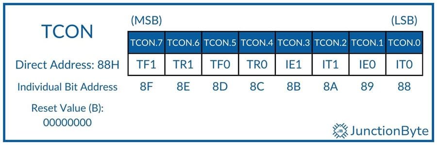
Timer Control (TCON) Register
While the name can be confusing, the lower four bits of the TCON register control some important aspects of the External Interrupts.
| Bit | Name | Description |
| TF1 | Timer 1 Overflow Flag | Set by hardware when Timer/Counter 1 Overflows. Can be cleared through software. Automatically cleared by hardware when the CPU executes an Timer 1 ISR at 001BH. |
| TR1 | Timer 1 Run Control Bit | TR1=1, Start Timer/Counter 1 TR1=0, Stops Timer/Counter 1 |
| TF0 | Timer 0 Overflow Flag | Set by hardware when Timer/Counter 0 Overflows. Can be cleared through software. Automatically cleared by hardware when the CPU executes an Timer 0 ISR at 000BH. |
| TR0 | Timer 0 Run Control Bit | TR0=1, Start Timer/Counter 0 TR0=0, Stops Timer/Counter 0 |
| IE1 | External Interrupt 1 Edge Detect Flag | Set by hardware when it detects an external interrupt on INT1 – P3.3. Automatically cleared by hardware when the CPU executes Interrupt 1 ISR (at 0013H) only if it is an edge-triggered interrupt. |
| IT1 | External Interrupt 1 Type Control Bit | IT1=1, INT1 is an Edge Triggered Interrupt (Falling Edge) IT1=0, INT1 is a Level Triggered Interrupt (Low Level) |
| IE0 | External Interrupt 0 Edge Detect Flag | Set by hardware when it detects an external interrupt on INT0 – P3.2. Automatically cleared by hardware when the CPU executes Interrupt 0 ISR (at 0003H) only if it is an edge-triggered interrupt. |
| IT0 | External Interrupt 0 Type Control Bit | IT0=1, INT0 is an Edge Triggered Interrupt (Falling Edge) IT0=0, INT0 is a Level Triggered Interrupt (Low Level) |
Interrupt Service Routine (ISR)
An ISR (Interrupt Service Routine) is a special function that runs when an interrupt occurs. Unlike regular functions, an ISR does not need a function call from the main program. The processor automatically jumps to the ISR when an interrupt occurs and resumes normal execution after the routine completes.
ISRs handle important and urgent tasks, such as reading sensor values, updating a display, or sending a signal to another device.
Characteristics of a Good ISR
- A well-designed ISR completes its task quickly to prevent unnecessary delays in program execution. Complex calculations or large data transfers inside an ISR slow down system performance.
- Functions like printf() and delay() introduce unnecessary execution time.
- Instead of handling complex tasks inside the ISR, it should only set flags or store minimal data. The main program should then process the information outside the ISR.
- An ISR cannot accept arguments or return a value. If data needs to be processed, the ISR should use global variables.
- The ISR must clear the interrupt flag before returning to prevent repeated triggers.
- If the ISR modifies a variable accessed by the main program, we should declare it as volatile.
Interrupt Vector Table (Memory Locations for Interrupts)
The 8051 microcontroller has a fixed memory addresses for each interrupt. These addresses, known as Interrupt Vectors, store the locations of Interrupt Service Routines (ISRs). When an interrupt occurs, the processor automatically jumps to the corresponding vector address and executes the ISR.
| Interrupt Number | Interrupt Type | Memory Address (Hex) |
| 0 | External Interrupt 0 (INT0) | 0003H |
| 1 | Timer 0 Interrupt (TF0) | 000BH |
| 2 | External Interrupt 1 (INT1) | 0013H |
| 3 | Timer 1 Interrupt (TF1) | 001BH |
| 4 | Serial Communication (RI/TI) | 0023H |
| 5 | Timer 2 Interrupt (TF2) (in 8052) | 002BH |
Since we will be writing C Programs in Keil µVision IDE with C51 Compiler, it is pretty straightforward to create C function as ISRs. The ISR must follow the following syntax and assign the appropriate interrupt number.
void interrupt_function(void) interrupt interrupt_number
For example, if we write the ISR as “void Timer0_ISR(void) interrupt 1,” the compiler will automatically assign the address 000BH to this function.
External Interrupts: INT0 and INT1
With the external interrupts, the 8051 microcontroller can respond to signals from external devices. The 8051 has two external interrupt sources, INT0 and INT1.
The INT0 and INT1 interrupts connect to pins P3.2 and P3.3, respectively. These pins detect changes in external signals and trigger an interrupt when an event occurs. INT0 executes its ISR from address 0003H, while INT1 uses 0013H.
Some applications that use external interrupts are: a push-button switch can generate an interrupt to wake up a system from sleep mode or motion sensors in security systems use interrupts to detect movement and trigger alarms.
To activate an external interrupt, we must configure the corresponding bit in the IE register. External interrupts can operate in edge-triggered or level-triggered mode.
In edge-triggered mode, an interrupt occurs when the input signal changes from HIGH to LOW. Setting IT0 or IT1 to 1 in the TCON register enables this mode. In level-triggered mode, the interrupt remains active as long as the input pin stays low. Clearing IT0 or IT1 to 0 in the TCON register enables level-triggered operation.
Timer Interrupts (TF0 and TF1)
The 8051 microcontroller has two timers, Timer 0 and Timer 1, which can generate interrupts when they overflow. These interrupts occur when the timer register reaches its maximum value and resets to zero. When a timer overflows, the corresponding TF0 or TF1 flag in the TCON register is set.
If we enable the interrupt, the microcontroller then executes the ISR assigned to the Timers (interrupt vector address of Timer 0 is 000BH and that of Timer 1 is 001BH).
We know that Timers work in different modes. In Mode 1, the timer functions as a 16-bit counter, counting from 0000H to FFFFH before overflowing. This mode provides accurate timing for delays and periodic tasks. In Mode 2, the timer functions as an 8-bit auto-reload counter, which automatically resets after reaching a predefined value. When the Timer register overflows from FFH to 00H, an interrupt occurs.
One of the common application of Timer Interrupts is Pulse Width Modulation (PWM) control. Since the 8051 Microcontroller doesn’t come with a built-in PWM hardware, we often use Timers to generate PWM signals. A timer interrupt generates pulses with precise duty cycle.
Serial Interrupts (RI, TI)
The serial communication interrupt occurs when the microcontroller completes sending or receiving a character. The 8051 has two serial interrupt flags in the SCON register: Receive Interrupt (RI) and Transmit Interrupt (TI).
The 8051 microcontroller sets the TI (Transmit Interrupt) flag when it finishes transmitting a byte of data through the SBUF register. It sets the RI (Receive Interrupt) flag when the microcontroller receives a full byte of data in the serial buffer (SBUF).
The serial interrupt vector address 0023H stores the location of the ISR that handles UART communication.
UART-based communication systems such as Bluetooth, GSM, and GPS modules can use interrupts for efficient data transfer.
Example C Programs for 8051 Microcontroller Interrupts
External Interrupt Example (Button Press Interrupt)
This program toggles an LED when a button press activates INT0 (External Interrupt 0).
#include <reg52.h>

sbit LED = P1^0;  /* Define LED Pin at P1.0 */
sbit Button = P3^2;  /* External Interrupt 0 Pin */

void ext_interrupt_ISR(void) interrupt 0
{
    LED = ~LED;  /* Toggle LED State */
}

void main()
{
  LED = 0;  /* Initialize LED state to OFF */
  EX0 = 1;  /* Enable External Interrupt 0 */
  EA = 1;   /* Enable Global Interrupts */
  TCON = 0x01;  /* Configure INT0 as Edge-Triggered */
  while(1);  /* Infinite Loop */
}
Working
- The program defines LED at P1.0 and Button at P3.2 (which corresponds to INT0).
- The ISR (ext_interrupt_ISR) toggles the LED state when the interrupt triggers.
- In the main() function, we are initializing the LED to OFF state.
- We are enabling INT0 by setting the EX0 and EA bits of the IE register.
- Next, we are configuring INT0 as ‘edge-triggered’ with the help of the TCON register (0x01).
- When the button connects P3.2 to GND, the microcontroller detects the signal and triggers INT0.
- The ISR toggles the LED, turning it ON if it was OFF and vice versa.
- The LED state changes with each button press.
Timer Interrupt Example (LED Blinking Using Timer)
This program blinks an LED using Timer 0 interrupt.
#include <reg52.h>

sbit LED = P1^0;  /* Define LED Pin as P1.0 */

void timer0_ISR(void) interrupt 1
{
  LED = ~LED;  /* Toggle LED State */
  TH0 = 0xFC;  /* Reload Timer 0 High Byte */
  TL0 = 0x66;  /* Reload Timer 0 Low Byte */
}

void main()
{
  LED = 0;     /* Initialize LED to OFF */
  TMOD = 0x01; /* Set Timer 0 in Mode 1 */
  TH0 = 0xFC;  /* Load Initial Timer Values */
  TL0 = 0x66;
  ET0 = 1;     /* Enable Timer 0 Interrupt
  EA = 1;      /* Enable Global Interrupts */
  TR0 = 1;     /* Start Timer 0 */
  while(1);    /* Infinite Loop */
}
Working
- The LED at P1.0 blinks based on Timer 0 overflow interrupt.
- The ISR (timer0_ISR) toggles the LED each time Timer 0 overflows.
- Using the TH0 (0xFC) and TL0 (0x66) values, we set the Timer for a 1ms delay.
- The TMOD register (0x01) configures Timer 0 in Mode 1 (16-bit Timer Mode).
- ET0 and EA bits of the IE register enables Timer 0 interrupt and global interrupts.
- TR0 starts Timer 0.
- The Timer interrupt executes every 1ms, toggling the LED state.
- The program functions without blocking other operations.
Serial Interrupt Example (UART Communication with Interrupt)
The following program transmits the character that the serial port receives (echo).
#include <reg52.h>

void serial_ISR(void) interrupt 4
{
  if (RI)
  {
    SBUF = SBUF;  /* Echo Received Character */
    RI = 0;  /* Clear Receive Interrupt Flag */
  }
  if (TI)
  {
    TI = 0; /* Clear Transmit Interrupt Flag */
  }
}

void main()
{
  SCON = 0x50;  /* Configure Serial Mode 1 (8-Bit UART) */
  TMOD = 0x20;  /* Set Timer 1 in Mode 2 (8-bit Auto-Reload Mode) */
  TH1 = 0xFD;   /* Load Timer 1 for 9600 Baud Rate */
  TL1 = 0xFD;   /* Initialize Timer 1 */
  TR1 = 1;      /* Start Timer 1 */
  ES = 1;       /* Enable Serial Interrupt */
  EA = 1;       /* Enable Global Interrupts */
  while(1);     /* Infinite Loop */
}
Working
- In the ISR serial_ISR(), the ‘if (RI) { … }’ checks if data has been received. It echoes the received character by storing in the SBUF and clears RI.
- The ‘if (TI) { … }’ checks for transmission completion and clears TI.
- We are configuring the Serial Port in Mode 1 (8-bit UART) using the SCON register (0x50).
- The TMOD (0x20) set the Timer 1 in Mode 2 (8-bit Auto-Reload) and the TH1 = 0xFD sets the Timer 1 for a Baud Rate of 9600.
- Then, we are enabling the serial interrupt with the help of ES and EA bits of the IE register.
- When the microcontroller receives a character via UART, it automatically transmits the same character back.
- The echo function performs data transmission without using the main loop.