In the previous guides, we explored two of the main hardware features of the 8051 Microcontroller i.e., Timers and UART. Sadly, that is where the ‘hardware capabilities’ of the vanilla 8051 Microcontroller ends. Yes. It has ‘interrupts’ but nothing that helps interfacing slightly advanced peripherals (sensors, displays, etc.). I am talking about I2C (I2C) and SPI. Let us focus on I2C for this guide. It is one of the simplest communication protocols and requires just two wires. Even though the 8051 Microcontroller doesn’t have the hardware for I2C Communication, we can use some software tricks to implement that. In this guide, let me explain everything you need to know about 8051 Microcontroller I2C Communication.
I will explain the basics of I2C Communication, how we can achieve I2C in 8051 Microcontroller through software (spoiler alert! bit-banging), and write a demo code using one of the popular I2C Modules (the PCF8574 IO Expander).
If you are new to 8051 Microcontroller, take a look at the 8051 Microcontroller Architecture guide. There I explained all the important internal components of the original 8051 Microcontroller.
What is I2C?
In embedded systems, communication protocols help in data exchange between devices. Serial communication protocols like UART, SPI, and I2C are very popular due to their simplicity and efficiency.
UART, for instance, is ideal for point-to-point communication, while SPI has higher data transfer rates for short-distance communication.
I2C, on the other hand, is quite unique for its ability to connect multiple devices using only two wires.
Inter-Integrated Circuit or I2C (more commonly I2C, pronounced I-Squared-C or I-Two-C) is a type of synchronous serial communication protocol. Philips Semiconductor (now NXP Semiconductors) developed the I2C protocol in the early 1980s to simplify communication between multiple integrated circuits on a single circuit board.
The two key points from the previous statement are ‘synchronous’ and ‘serial.’ The protocol operates synchronously, meaning it uses a clock signal to coordinate data transfer. Next, the data transfer is serial in nature i.e., it sends one bit at a time over a single wire.
I2C protocol enables communication using only two signal lines/wires: Serial Data Line (SDA) and Serial Clock Line (SCL) to reduce wiring complexity and save space. The SDA line carries the actual data, while the SCL line synchronizes the communication by providing the clock signal.
Soon, I2C became one of the widely used serial communication protocols for connecting low-speed devices (sensors and memory devices).
I2C Communication Basics
I2C operates using a master-slave architecture. The master initiates communication and controls the clock signal while there can be one or more slave devices on the bus. Each slave device has a unique address so that the master can select a specific device for communication.
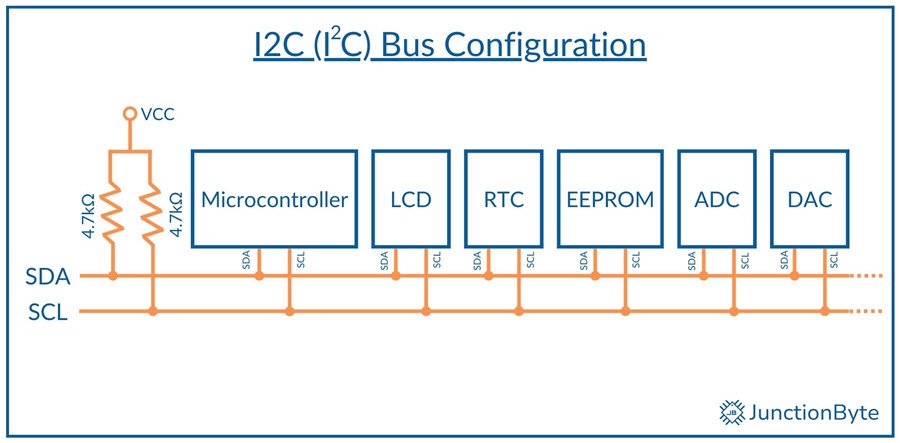
The protocol supports two addressing formats: 7-bit and 10-bit. While 7-bit addressing allows up to 128 unique devices on the same bus, 10-bit addressing expands this limit to 1024 devices. The master generates the clock signal, and both SDA and SCL lines operate in an open-drain configuration.
You need to add pull-up resistors to both the SDA and SCL Lines. A 4.7kΩ resistor works well for standard mode (100 kbps).
NOTE: The ‘master-slave’ terminology has had some backlash in recent times. Many are calling it ‘outdated’ and ‘politically incorrect.’ There are some alternatives such as ‘primary-secondary,’ ‘leader-follower,’ ‘controller-worker,’ ‘controller-target,’ etc. For the sake of simplicity, I will continue to use the original ‘master-slave’ terminology. I mean no harm.
I2C Data Transfer Process
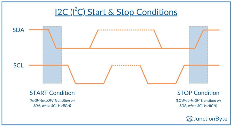
The I2C data transfer process begins with the master generating a START condition, which is a HIGH-to-LOW transition on the SDA line while SCL remains HIGH. This action alerts all connected devices that communication is starting.
After the start condition, the master transmits the address of the target slave device (7 or 10 bits), followed by a read/write bit to indicate the desired operation. A ‘0’ in this bit signals a write operation, whereas a ‘1’ indicates a read operation.
After each byte of data, the receiving device sends an acknowledgment (ACK) bit to confirm successful reception. If multiple devices share the bus, only the addressed device acknowledges the request by pulling the SDA line LOW.
If no device responds, the master interprets it as a non-acknowledgment (NACK) and may retry or abort the communication. So, each data frame in I2C consists of 8 bits followed by an ACK or NACK signal from the receiving device.
Once addressing is complete, the master initiates read or write operations. In write mode, data moves from the master to the slave, while read mode allows the master to receive data.
Finally, the master concludes the communication with a STOP condition, where it releases the SDA line to transition from LOW to HIGH while keeping SCL HIGH.
I2C Speed Modes
The following table indicates various I2C bus speeds:
| I2C Mode | Maximum Clock Speed (Data Rate) | Pull-up Resistor | Bus Capacitance |
| Standard Mode (Sm) | 100 kHz (100 kbps) | 4.7 kΩ – 10 kΩ | 400 pF |
| Fast Mode (Fm) | 400 kHz (400 kbps) | 1 kΩ – 4.7 kΩ | 400pF |
| Fast Mode Plus (Fm+) | 1 MHz (1 Mbps) | 0.47 kΩ – 1 kΩ | 550 pF |
| High-speed Mode (Hs-mode) | 3.4 MHz (3.4 Mbps) | 0.22 kΩ – 0.47 kΩ | 100 pF |
| Ultra-fast Mode (UFm) | 5 MHz (5 Mbps) | No pull-up (Push-Pull) | 50 pF |
The Standard Mode is the original I2C specification with clock speed of 100 kHz and communication speeds up to 100 kbps. Over time, several modes are added to the specification. The first four modes i.e., Standard, Fast, Fast Mode Plus, and High-speed Mode support bidirectional buses with open-drain (or open-collector) configuration. Coming to the Ultra-fast Mode, it is a unidirectional bus with a push-pull driver.
Bus Capacitance determines the limit of the number of devices connected to the bus.
Does 8051 Microcontroller Support I2C?
The MCS-51 Architecture or the 8051 Microcontroller is a rather simple device. Its internal architecture lacks several hardware features when you compare it to modern ARM architecture.
Importantly, the 8051 Microcontroller lacks native support for the Inter-Integrated Circuit (I2C) communication protocol.
Despite the absence of built-in I2C functionality, we can still implement I2C on the 8051 using a technique called Bit-banging.
8051 Microcontroller I2C Implementation Through Bit-banging
Bit-banging is a process of manually toggling the I/O pins to simulate the I2C protocol’s timing and signalling. This method requires precise timing and careful programming and it allows the 8051 to communicate with I2C-compatible devices such as sensors, displays, and memory chips.
To implement I2C on an 8051 Microcontroller through bit-banging, we must write software routines to control the clock (SCL) and data (SDA) lines of the I2C bus. The software must generate start and stop conditions, manage acknowledgments, and handle data transmission and reception.
While this approach works effectively, it consumes more CPU resources compared to microcontrollers with dedicated I2C hardware.
8051 Microcontroller I2C Example
8051 I2C Driver
First, let us implement the basic I2C Driver for 8051 Microcontroller. This driver includes the four basic function:
- Start I2C Communication
- Stop I2C Communication
- Write Data to I2C Device
- Read Data from I2C Device (With ACK or NACK)
#ifndef AT89S52_I2C_H_
#define AT89S52_I2C_H_

/* Include the Main 8051 Header File */
#include <reg52.h>
/* This header is necessary for using NOP */
#include <intrins.h>

/* Define two GPIO Pins, one for SDA and one for SCL */
sbit SDA = P3^6; /* Define SDA Pin */
sbit SCL = P3^7;  /* Define SCL Pin */

/* I2C Function Prototypes */
bit I2C_Start(void);
bit I2C_Stop(void);
bit I2C_Write(unsigned char datax);
unsigned char I2C_Read(unsigned char ack);

/* I2C Function Definitions */

/* The I2C_Start function creates the START condition.
 * Pull SDA LOW while SCL is HIGH. */
bit I2C_Start(void)
{
  SCL = 0;
  SDA = 1;
  _nop_ ();
  SCL = 1;
  _nop_ ();
  SDA = 0;
  _nop_ ();
  SCL = 0;
  return 1;
}

/* The I2C_Stop function creates the STOP condition.
 * Pull SDA HIGH while SCL is HIGH. */
bit I2C_Stop(void)
{
  SCL = 0;
  _nop_ ();
  SDA = 0;
  _nop_ ();
  SCL = 1;
  _nop_ ();
  SDA = 1;
  return 1;
}

/* The I2C_Write Function Transmits one byte (8 bits) over the I2C bus.
 * The MSB (Most Significant Bit) is sent first.
 * After all 8 bits are sent,
 * SDA is released to receive an acknowledgment (ACK)
 * from the slave. */

bit I2C_Write(unsigned char datax)
{
  unsigned char i;
  for (i = 0; i < 8; i++)
  {
    SDA = datax & 0x80;
    _nop_ ();
    SCL = 1;
    _nop_ ();
    SCL = 0;
    datax = datax << 1;
  }
  SDA = 1;
  _nop_ ();
  SCL = 1;
  _nop_ ();
  if (SDA == 0)
  {
    SCL = 0;
    _nop_ ();
    return 1;
  }
  SCL = 0;
  _nop_ ();
  return 0;
}

/* The I2C_Read Function Reads 8 bits from the I2C slave.
 * Stores received bits in datax.
 * ACK (1) is sent if more data is expected.
 * Otherwise NACK (0) is sent. */

unsigned char I2C_Read(unsigned char ack)
{
  unsigned char i, datax = 0;
  SDA = 1;  /* Release SDA for reading */
  for (i = 0; i < 8; i++)
  {
    SCL = 1; /* Generate clock pulse */
    datax = (datax << 1) | SDA; /* Read the bit */
    SCL = 0; /* Bring SCL low */
  }

  if (ack)
  {
    SDA = 0; /* Pull SDA LOW to Send ACK */
    _nop_ ();
    SCL = 1; /* Generate clock for ACK */
    _nop_ (); /* Wait for Some time */
    SCL = 0;  /* Bring SCL low */
    _nop_ ();
    SDA = 1; /* Pull SDA back to HIGH */
  }
  else
  {
    SDA = 1; /* Send NACK */
    _nop_ ();
    SCL = 1; /* Generate clock for NACK */
    _nop_ (); /* Wait for Some time */
    SCL = 0;  /* Bring SCL LOW */
    _nop_ (); /* Wait for Some time */
    SCL = 1;
  }
  return datax; // Return the data read
}

#endif
8051 I2C Scanner
Before looking at the actual I2C Demo code for the 8051 Microcontroller, I wrote a useful I2C Scanner program that helps you identify the I2C Slave address. This application uses the previous I2C Driver file and adds UART functionality to print the results on to a Serial Terminal.
#include <reg52.h>
#include <stdio.h>
#include "at89s52_i2C.h"

/* Function Prototypes */
void UART_Init(void);
void UART_SendByte(unsigned char datax);
void UART_SendString(char* str);
void UART_SendInt(int num);

bit I2C_Scan(unsigned char address);

/* UART Initialization Function */
void UART_Init(void)
{
  TMOD = 0x20;  /* Timer 1 in Mode 2 (8-bit Auto-reload)*/
  TH1 = 0xFD;   /* Set Timer reload value for 9600 Baud Rate */
  TL1 = 0xFD;
  TR1 = 1;      /* Start Timer 1 */
  SCON = 0x50;  /* Serial Mode 1 (8-bit UART), Enable Receiver */
  TI = 1;       /* Set TI to indicate ready to send */
}

/* UART Send Byte */
void UART_SendByte(unsigned char datax)
{
  SBUF = datax;  /* Load the byte into the transmit buffer */
  while (!TI);  /* Wait for the byte to be transmitted */
  TI = 0;       /* Clear the transmit interrupt flag */
}

/* UART Send String */
void UART_SendString(char* str)
{
  while (*str)
  {
    UART_SendByte(*str);
    str++;
  }
}

/* Function to Display HEX numbers on Serial Terminal */
void UART_SendInt(int num)
{
  char digits[3];  /* To store the hexadecimal digits */
  char i = 0;

  /* Handle if the number is zero */
  if (num == 0)
  {
    UART_SendByte('0');
    return;
  }

  /* Convert the integer to hexadecimal representation */
  while (num > 0)
  {
    int rem = num % 16;
	if (rem < 10)
	{
	  digits[i] = rem + '0';  /* Convert 0-9 to '0'-'9' */
    }
	else
	{
	  digits[i] = rem - 10 + 'A';  /* Convert 10-15 to 'A'-'F' */
	}
	num /= 16;
    i++;
  }

  /* Print digits in reverse order */
  for (i--; i >= 0; i--)
  {
    UART_SendByte(digits[i]);
  }
}

/* I2C Scan Function */
bit I2C_Scan(unsigned char address)
{
  unsigned char ack;

  if (!I2C_Start())
  {
    UART_SendString("Start failed\n");
    return 0;  /* Start condition failed */
  }

  ack = I2C_Write(address << 1);  /* Send device address (shifted for write) */
  if (!ack)
  {
    I2C_Stop();  /* Stop communication if no ACK */
    return 0;  /* No ACK means no device at this address */
  }

  I2C_Stop();  /* Send stop condition */
  return 1;  /* Device found and acknowledged */
}

/* Main Program to Scan I2C Devices */
void main(void)
{
  unsigned char address;

  UART_Init(); // Initialize UART for printing
  UART_SendString("I2C Scan Started...");

  for (address = 0x00; address <= 0x7F; address++)
  {
    if (I2C_Scan(address))
    {
      UART_SendString("\nDevice found at 0x");
	  UART_SendInt(address);
    }
  }

  UART_SendString("\nI2C Scan Completed.\n");

  while(1); /* Infinite loop to stop program execution */
}
You can use this program with AT89S52 Microcontroller (or any 8051 Microcontroller) and find out the I2C Slave Addresses.
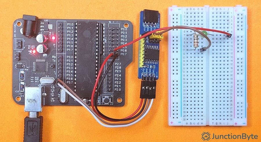
I connected a couple of I2C Modules in daisy chain configuration and here’s what the serial terminal (RealTerm) displayed.
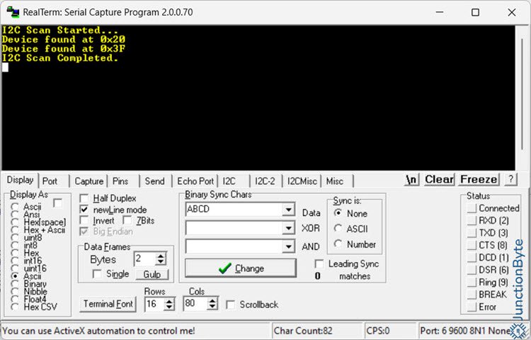
We can use these addresses in our applications while using the I2C Devices. Here, 0x20 is the address of the PCF8574 IO Expander Module, while 0x3F is the address of the PCF8574 I2C LCD Module.
8051 Microcontroller I2C Demo (PCF8574)
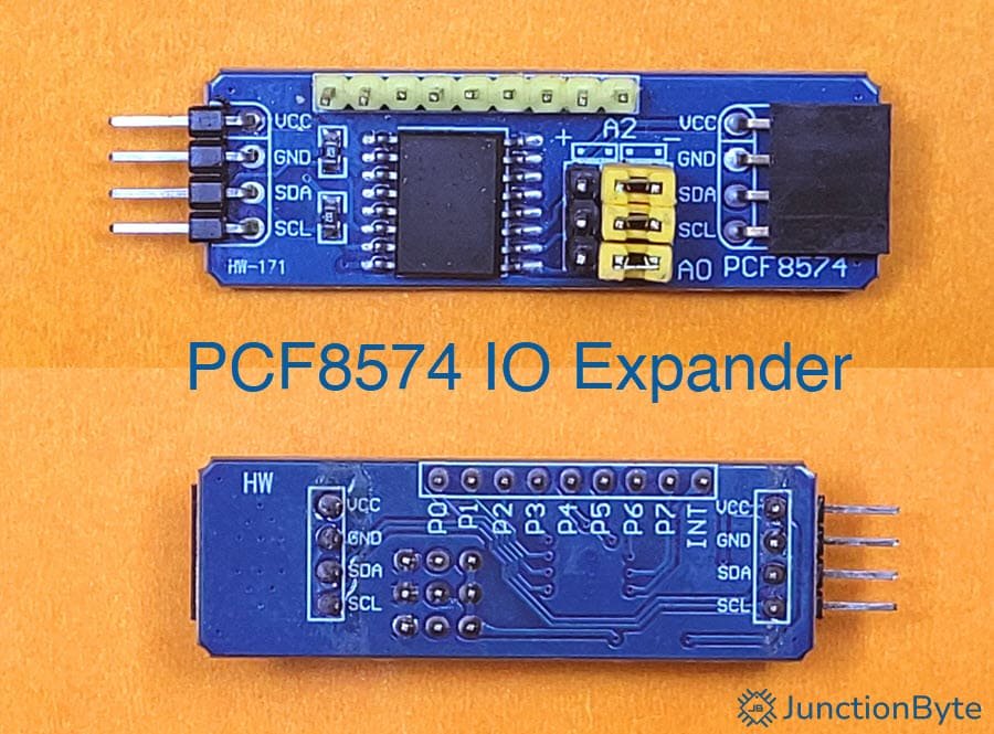
Using the I2C Driver as base, we can assign I2C functionality to the 8051 Microcontroller and communicate with any I2C Devices. One of the simplest I2C Devices/Modules is the PCF8574 IO Expander. Any microcontroller can interface with PCF8574 using I2C and expand its IO capabilities up to 8 more pins.
PCF8574 Driver
First, I will write a driver for the PCF8574 IC using the previous I2C Driver. Then, using both these drivers, I will write a simple application to control IO Pins of the PCF8574 Module from an 8051 Microcontroller.
#ifndef AT89S52_PCF8574_H_
#define AT89S52_PCF8574_H_

/* Include the I2C Header File */
#include "at89s52_i2c.h"

/* A Static Variable for PCF8574 Address */
static unsigned char PCF8574_Address;

/* PCF8574 Function Prototypes */
void PCF8574_Init(unsigned char address);
void PCF8574_Write(unsigned char datax);
unsigned char PCF8574_Read();
void PCF8574_GPIO_Write(unsigned char pin, unsigned char value);
unsigned char PCF8574_GPIO_Read(unsigned char pin);
void PCF8574_GPIO_Toggle(unsigned char pin);

/* PCF8574 Function Definitions */

/* PCF8574_Init stores the PCF8574 I2C address for use in later functions.
 * Only called once at the beginning of the program. */
void PCF8574_Init(unsigned char address)
{
  PCF8574_Address = address << 1;
}

/* PCF8574_Write writes an 8-bit value (datax)
 * to all PCF8574 GPIO pins at once.
 * Sends I2C START, device address, data, then I2C STOP. */
void PCF8574_Write(unsigned char datax)
{
  I2C_Start();
  I2C_Write(PCF8574_Address);
  I2C_Write(datax);
  I2C_Stop();
}

/* PCF8574_Read reads 8-bit input data from PCF8574 pins.
 * The address is sent with read mode (last bit = 1).
 * The received byte is returned. */
unsigned char PCF8574_Read ()
{
  unsigned char datax;
  I2C_Start();
  I2C_Write (PCF8574_Address | 0x01); /* Read Mode */
  datax = I2C_Read(1); /* Read with ACK */
  I2C_Stop();
  return datax;
}

/* PCF8574_GPIO_Write reads the current state of all pins.
 * Modifies only the desired pin using bitwise operations.
 * Writes updated data back to the PCF8574. */
void PCF8574_GPIO_Write(unsigned char pin, unsigned char value)
{
  unsigned char datax = PCF8574_Read();
  if (value)
  {
    datax |= (1 << pin);
  }
  else
  {
    datax &= ~(1 << pin);
  }
  PCF8574_Write(datax);
}

/* PCF8574_GPIO_Read reads all GPIO pin states.
 * Extracts the requested pin value using bit masking. */
unsigned char PCF8574_GPIO_Read(unsigned char pin)
{
  unsigned char datax = PCF8574_Read();
  return (datax & (1 << pin)) ? 1 : 0;
}

/* PCF8574_GPIO_Toggle reads current pin states.
 * XOR operation flips the selected bit (0 ? 1, 1 ? 0).
 * Writes updated value back to the PCF8574. */
void PCF8574_GPIO_Toggle(unsigned char pin)
{
  unsigned char datax = PCF8574_Read();
  datax ^= (1 << pin);
  PCF8574_Write(datax);
}

#endif
8051 PCF8574 Demo
Using the I2C and the PCF8574 Drivers, I created a simple application that demonstrates the capabilities of these drivers.
#include <reg52.h>

/* Include the Header File containing the PCF8574 Driver */
#include "at89s52_pcf8574.h"

/* Define the Address for PCF8574 Module */
/* Adjust according to your hardware setup */
#define PCF8574_ADDRESS 0x20

/* Create a Delay Function */
void delay_ms(unsigned int ms)
{
  unsigned int i, j;
  for (i = 0; i < ms; i++)
  {
    for (j = 0; j < 120; j++);
  }
}

void main()
{
  unsigned char pin1_state = 0;
  PCF8574_Init(PCF8574_ADDRESS);
  /* Write all pins to 0xFF (all HIGH) */
  PCF8574_Write(0xFF);
  delay_ms(1000);
  /* Write all pins to 0x00 (all LOW) */
  PCF8574_Write(0x00);
  delay_ms(1000);
  while (1)
  {
    /* Toggle Pin 0 */
    PCF8574_GPIO_Toggle(0);
    delay_ms(500);
    /* Read Pin 1 state */
    pin1_state = PCF8574_GPIO_Read (1);
    /* Set Pin 2 according to Pin 1 state */
    PCF8574_GPIO_Write(2, pin1_state);
    delay_ms(10);
  }
}
Conclusion
A very useful guide on how to implement I2C Protocol in 8051 Microcontroller. We have several I2C devices and sensors (displays, RTC, etc.) that are now easy to add to your 8051 Microcontroller projects. The 8051 Microcontroller I2C driver is important for some of the upcoming guides such as Interfacing PCF8574 I2C LCD with 8051 Microcontroller or adding RTC capabilities to 8051 Microcontroller.