If LEDs are some of the simplest ‘output’ devices for a microcontroller, then their ‘input’ counterparts are Push Buttons. They are one of the simplest and most commonly used human-machine interface (HMI) components. They allow us to interact with embedded systems by sending signals (either LOW or HIGH) to the microcontroller when pressed or released. So, in this guide, I will explain everything you need to know about Interfacing Push Button with 8051 Microcontroller.
What makes ‘Push Buttons’ an essential part of modern embedded systems?
- Low-cost: They are inexpensive and easy to use.
- Simple interface: Push buttons have a straightforward ON/OFF (binary) input which is very easy for any microcontroller to interpret.
- Versatile: You can use them in a variety of applications ranging from basic control systems to more complex systems.
By using Push Buttons in Embedded Systems, we can achieve the following functions:
- Trigger actions (for example, turn ON/OFF an LED, Start/Stop a motor, etc.).
- Send input for user interface applications.
- Reset devices or systems (e.g., hardware reset).
In a previous guide, I showed you all about Interfacing an LED with an 8051 Microcontroller. There, I also write a very useful GPIO driver (or a library file, if you must). Refer to that guide where I have explained all the important aspects of the GPIO driver. Needless to say, I will be using the same driver here to write an application to interface a simple Push Button with an 8051 Microcontroller.
Components Needed
Here is everything you need to connect a Push Button with the 8051 Microcontroller and use it as an Input device.
- 8051 Microcontroller: I will be using an AT89S52 Microcontroller for this project that will control the button input. You can use any variant of the 8051 Microcontroller with little to no changes in the procedure.
- Push Button: A simple mechanical switch used to generate an input binary signal (HIGH/ON or LOW/OFF) to the microcontroller.
- LED: To indicate the state of the system based on the push button input, we can use a simple LED as an output device.
- Current Limiting Resistor (for LED): Don’t forget a small series resistor (220Ω or 330Ω) to limit the current flowing through the LED.
- Breadboard and Jumper Wires: For connecting all the components.
Keep in mind that the 8051 Microcontroller needs some additional components in order to work properly. This is known as the Minimal Circuit for 8051 Microcontroller. I’ve spoken about these in my 8051 Pin Diagram and Pin Description guide. Do check it out.
The 8051 Microcontroller Minimal Circuit includes: a reset circuit, a clock circuit, pull-up resistors for the Port 0 (P0) pins, and pulling the EA pin HIGH (as we will be using the internal memory of the microcontroller).
If you are using a development board, then there is a good chance that it has all these essential components. In case you are building the circuit from scratch, then make sure you include those components as well.
Circuit Design for Interfacing a Push Button with 8051 Microcontroller
Push Button Interfacing
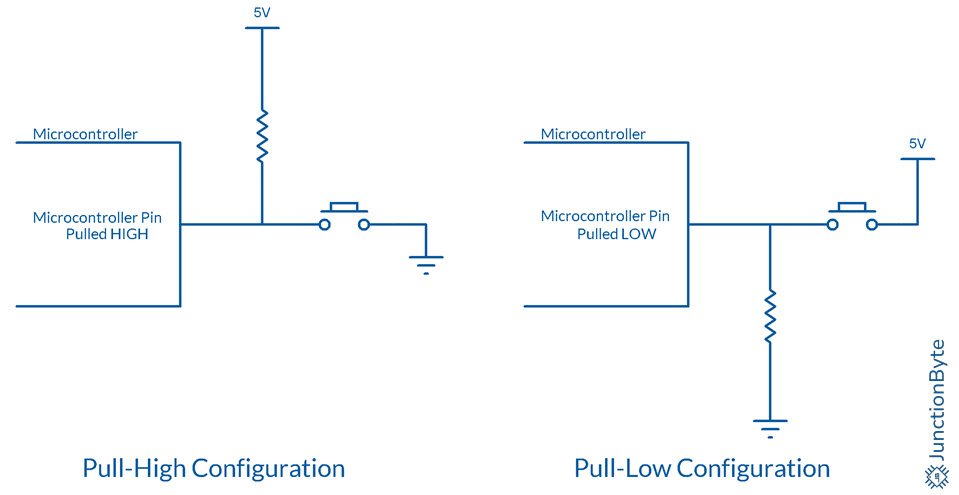
When you interface a push button with any microcontroller, there are two ways to handle the signal:
- Pull-up resistor: In this case, the input pin of the microcontroller is kept HIGH (Logic Level 1) through the resistor when you are not pressing the button. When you press/push the button, the pin goes LOW (Logic Level 0).
- Pull-down resistor: This is the reverse, where the microcontroller pin is normally LOW (Logic Level 0) through the resistor (when you do not press the button), and HIGH (Logic Level 1) when you push it.
If you remember from the ‘8051 Microcontroller Pin Diagram and Pin Description’ guide, all the I/O Ports (except Port 0) have internal pull-up resistors. Even with Port 0 Pins, we will be adding external pull-up resistors.
So, essentially all the 32 I/O pins of the 8051 Microcontroller already have pull-up resistors. We need not add a pull-up resistor if we want to use a particular Pin as Input and connect it to a Push Button.
In this guide, we’ll use the ‘pull-up resistor configuration’ by using the internal pull-up resistors.
We can connect one end (pin/terminal) of the button to ground (GND) and the other pin directly to a Port Pin. This configuration makes the pin read 1 when the button is not pressed and 0 when the button is pressed.
Circuit Diagram
I made the following connection to demonstrate the Push Button:
- I used the Pin P1.1 (Port 1, Pin 1) of the AT89S52 Microcontroller as the input pin.
- Then, I connected a push button between P1.1 and ground (GND).
- To indicate the change in state of the button, I used a 5mm Green LED with a 220Ω resistor.
- I connected the anode of the LED to +5V, the cathode of the LED to one end of the resistor, and the other end of the resistor to P1.0 (Port 1, Pin 0). The Pin P1.0 acts as an output pin.
The final circuit will look like this:
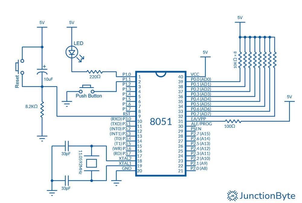
When the button is not pressed, P1.1 is pulled HIGH to +5V via the internal pull-up resistor. When the button is pressed, P1.1 is pulled LOW to 0V (ground), and the microcontroller detects a logical 0.
Code for AT89S52 to Interface the Push Button
Let’s now move on to writing the code. This C program will:
- Continuously monitor the state of the push button.
- Turn ON an LED connected to P1.0 when the button is pressed.
- Turn OFF the LED when the button is not pressed.
Code Structure
- Initialization: Set the necessary I/O pins as input or output.
- Button Monitoring: Continuously check the state of the button.
- Debouncing: Add a small delay to handle the mechanical bounce of the push button (debouncing).
- LED Control: Turn the LED ON/OFF based on the push button state.
Code
Here is the complete code:
/*Include the header file for the 8051 microcontroller*/
#include <REG52.H>

/*Declare a variable of type 'sbit' for the Port Pin connected to the Push Button*/
sbit BUTTON_PIN = P1^1;
/*Declare a variable of type 'sbit' for the Port Pin connected to the LED*/
sbit LED_PIN = P1^0;

/*Function prototype for Delay*/
void delay_ms(unsigned int ms); /*Delay Function Declaration*/

/*Main Function*/
void main()
{
  /*Main loop*/
  while(1)
  {
    /*Initialize Port Pin 0 as output (LED) and Pin 1 as input (Button)*/
    P1 = 0xFE; /*Rest of the Pins are initialized as Inputs*/
    /*Check if the Push Button is pressed*/
    if (BUTTON_PIN == 0)
    {
      /*Since it is an Active-LOW Push Button (pressed = 0)*/
      delay_ms(10);  /*Call the delay function to debounce the switch*/
      /*Recheck the push button state after debounce delay*/
      if (BUTTON_PIN == 0)
      {
        /*If button is still pressed after delay*/
	/*Execute an action when button is pressed*/
	/*For example, turn ON the LED connected to Pin P1.0*/
	LED_PIN = 0; /*Pin P1.0 acts as a 'sink' for LED. 0=ON, 1=OFF*/
      }
    }
    else
    {
    /*Turn OFF the LED connected to Pin P1.0*/
    LED_PIN = 1;
    }
  }
}

/*Delay function to generate a time delay in milliseconds*/
void delay_ms(unsigned int ms)
{
  unsigned int i, j;
  for(i = 0; i < ms; i++)
  {
    for(j = 0; j < 1275; j++)
    {
      /*No operation: This creates a time delay by looping a large number of times*/
      /*The number of iterations is calibrated to approximately 1 ms*/
    }
  }
}
Explanation of the Code
Let’s break down the code step by step:
1. Including the 8051 Header
#include <REG52.H>
This header file contains all the necessary register definitions for the 8051 microcontroller. It includes the memory-mapped register addresses for I/O ports and other peripherals.
2. Defining the Button and LED Pins
sbit BUTTON_PIN = P1^1;  // Push Button is connected to P1.1

sbit LED_PIN = P1^0;     // LED is connected to P1.0
We have to use the ‘sbit’ data type of Keil C51 Compiler to define bit-addressable pins of a Port. Here, ‘BUTTON_PIN’ is a variable of type ‘sbit’ and it is assigned to Bit 1 of Port 1 (P1.1). Similarly, the ‘LED_PIN’ refers to the LED connected to Bit 0 of Port 1 (P1.0).
3. Main Function
void main()
{
  /*Main loop*/
  while(1)
  {
    /*Initialize Port Pin 0 as output (LED) and Pin 1 as input (Button)*/
    P1 = 0xFE; /*Rest of the Pins are initialized as Inputs*/
    /*Check if the Push Button is pressed*/
    if (BUTTON_PIN == 0)
    {
      /*Since it is an Active-LOW Push Button (pressed = 0)*/
      delay_ms(10);  /*Call the delay function to debounce the switch*/
      /*Recheck the push button state after debounce delay*/
      if (BUTTON_PIN == 0)
      {
        /*If button is still pressed after delay*/
        /*Execute an action when button is pressed*/
        /*For example, turn ON the LED connected to Pin P1.0*/
        LED_PIN = 0; /*Pin P1.0 acts as a 'sink' for the LED. 0=ON, 1=OFF*/
      }
    }
    else
    {
      /*Turn OFF the LED connected to Pin P1.0*/
      LED_PIN = 1;
    }
  }
}- Initialization: We are initializing Pin 0 of Port 1 as Output and Pin 1 of Port 1 as Input.
- Button Press Detection: Next, we are checking the button state. If the button is pressed (P1.1 is LOW), we wait for a short time (delay_ms(10)) to avoid bouncing.
- LED Control: If the button is still pressed after the debounce delay, the LED is turned ON. If the button is not pressed, the LED is turned OFF.
4. Debounce Function
void delay_ms(unsigned int ms)
{
  unsigned int i, j;
  for(i = 0; i < ms; i++)
  {
    for(j = 0; j < 1275; j++)
    {
      /*No operation: This creates a time delay by looping a large number of times*/
      /*The number of iterations is calibrated to approximately 1 ms*/
    }
  }
}
This is a simple delay function that generates an approximate 1ms delay by using nested loops. We are using this function to debounce the switch and avoid detecting multiple transitions when the button is pressed.
Compile and Run the Code
- Step 1: Create a Project: Open Keil uVision, create a new project, and set AT89S52 as the target device.
- Step 2: Write the Code: Create a new ‘main.c’ file and write the code.
- Step 3: Configure Target Options: In the ‘Target Options’ window, enable generation of the HEX file.
- Step 4: Compile the Code: Build the project and make sure there are no errors.
- Step 5: Program the Microcontroller: Use a programmer (e.g., USBasp or another compatible device) to load the compiled hex file onto the AT89S52 microcontroller using ProgISP (or other similar software).
- Step 6: Test the Circuit: Connect the push button and LED as per the circuit diagram, and observe the behavior.
Conclusion
In this guide, we learned how to interface a push button with the 8051 microcontroller and write a simple C program to control an LED based on the button press.
I explained all the important aspects of the projects such as the importance of push buttons, how to design the circuit, and how to write the C code. I hope that this guide could help you in interfacing a push button with a 8051 Microcontroller. If you did not understand anything or have any difficulty implementing the project, do let me know through the comments section.