The main purpose of any microcontroller is to control a bunch of input/output devices. We saw some basic I/O devices such as LEDs, Push Buttons, 16×2 LCD working seamlessly with the 8051 Microcontroller. What if your application needs to send some information to a computer? How about exchanging information with a Bluetooth Module? One of the easiest ways to achieve this is through Serial Communication. While the 8051 Microcontroller may not have a whole lot of internal peripherals, they do have a Serial Communication Port. In this guide, let us learn everything about the 8051 Microcontroller UART or Serial Port.
First, we will look at some basics of Serial Communication. Then, we will understand the 8051 Microcontroller UART (Serial) Hardware (registers, modes of operation, baud rate, etc.).
In the previous guide, we saw 8051 Microcontroller Timers. As we will be using some aspects of the Timer for Baud Rate Generation, I highly recommend you go through that guide before proceeding further.
Introduction to Serial Communication
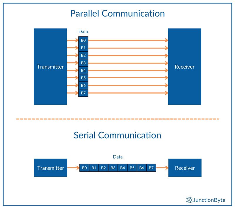
If you look at the internal communication of a microcontroller, it is usually parallel. Parallel communication sends multiple bits of data simultaneously using multiple wires. In the case of 8051 Microcontroller, the communication involves transfer of 8 bits using the data bus (which is, well, 8-bit wide).
What about communication outside the microcontroller? Parallel Communication is definitely fast but requires more connections (technically, one wire per bit). This leads to higher costs and hardware complexity.
Therefore, for long distance communication and communication outside the microcontroller, Serial Communication is the preferred choice.
Serial communication is a process of sending data one bit at a time over a single communication channel/wire. This method of communication reduces the number of required connections, lowers the cost and complexity of circuits. It also allows communication over longer distances with minimal signal degradation.
So, a microcontroller converts the internal parallel data to serial form and then transmits it over one or two wires, one bit at a time. When the microcontroller receives serial data, it converts the data into parallel form so that internal data processing becomes seamless.
Types of Serial Communication
We can divide serial communication into two primary modes: Synchronous and Asynchronous.
Synchronous communication uses a shared clock signal between sender and receiver to coordinate data transfer. Both devices stay in sync because the clock controls data timing (hence the name Synchronous Communication).
This method allows for faster and more reliable data transfer with precision timing. Synchronous Communication is suitable for high-speed applications like memory interfaces and display connections.

On the other hand, Asynchronous communication does not rely on a shared clock signal between devices. Instead, it uses start and stop bits to frame each data byte and define the beginning and end of data transmission. Both devices must agree on the baud rate before communication begins.
Serial Communication Protocols
There are several protocols that govern serial communication. UART (Universal Asynchronous Receiver/Transmitter) is a common protocol for asynchronous communication. It is one of the standard protocols in several microcontrollers (including the 8051 Microcontroller).
SPI (Serial Peripheral Interface) supports high-speed synchronous communication and is popular in memory and display applications. I2C (Inter-Integrated Circuit) is another popular synchronous communication protocol with support for multiple devices to share a single bus.
Even though I2C uses a clock signal, it still has start and stop conditions i.e., it combines features of both synchronous and asynchronous communication. Sensors, RTC, etc. use I2C for data transfer.
What is UART?
UART or Universal Asynchronous Receiver/Transmitter is the hardware communication protocol responsible for asynchronous communication to transmit data one bit at a time. Many microcontrollers, computers, and embedded systems use UART to send and receive serial data over short and medium distances.
A typical UART system consists of two main components: a transmitter and a receiver. The transmitter converts parallel data into a serial format before sending it. The receiver converts the incoming serial data back into parallel format. These two UART modules work independently and allow for a full-duplex communication i.e., data can be sent and received simultaneously.
How UART Works (UART Data Frame Structure)
UART transmits data by sending bits sequentially over a single wire. The transmission or the UART data frame begins with a start bit, which signals the receiver to prepare for incoming data. The start bit is always a low signal.
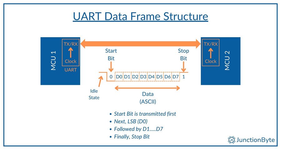
After the start bit, the frame includes 5 to 9 data bits, which is the actual data being sent. The number of data bits depends on the specific application and configuration. We commonly use 8-bit data packets to represent a Byte of data.
Next, an optional parity bit may appear. It helps in detecting errors during transmission. The parity bit can be set to even, odd, or omitted entirely.
Finally, the frame ends with one or two stop bits to indicate the completion of the data packet (or end of frame). The stop bit(s) are always high.
The most common UART data frame is 8N1 i.e., 8 data bits, no parity, and one stop bit.
UART Baud Rate
The baud rate defines the speed of data transmission in UART communication. It is measured in bits per second (bps). Baud Rate determines how quickly data moves between devices.
Common baud rates include 1200, 2400, 4800, 9600, 19200, 38400, 57600, and 115200 bps. The 9600 baud rate is popular for basic applications due to its balance of speed and reliability. Higher rates like 115200 bps are often used in modern systems where faster data transfer is necessary, such as in high-performance microcontrollers or IoT devices.
Both devices (transmitter and receiver) must use the same baud rate to communicate correctly. If the baud rates do not match, data corruption or loss can occur.
Signal Levels & Hardware
UART communication relies on specific voltage levels to transmit data accurately. TTL (Transistor-Transistor Logic) levels are very common in microcontrollers. They operate at low voltages, typically 0V for logic low and 3.3V or 5V for logic high.
In contrast, RS-232, a standard for serial communication, uses higher voltage levels. While the RS-232 Standard defines a variety of voltage level0 (up to ±25V)s, ±12V and ±15V are very popular (+12V or +15V for logic 0 and -12V or -15V for logic 1).
These higher voltages make RS-232 more suitable for longer-distance communication, as they reduce susceptibility to noise and interference.
To bridge the gap between TTL and RS-232 levels, devices like the MAX232 play a key role. These ‘drivers’ adjust voltage levels and enable communication between microcontrollers and PCs or other RS-232-compatible devices.
Most modern computers do not have RS232 COM Ports anymore as USB replaced them all. This is where FTDI converters come into play. They act as USB-to-serial data converters and allow modern computers to interface with microcontrollers and other legacy serial devices.
8051 Microcontroller UART Hardware Overview
The 8051 microcontroller includes a built-in serial communication interface (UART). This makes it easier to connect with computers, sensors, and external devices (GPS Receivers, GSM Modules, and Bluetooth Devices).
In terms of physical pins, the 8051 microcontroller uses two dedicated pins for UART communication: RXD (P3.0) and TXD (P3.1). The TXD pin transmits serial data from the microcontroller to external devices, while the RXD pin receives incoming data. These pins connect directly to the UART module.
The three main components of the 8051 Microcontroller UART Module are: the transmitter, receiver, and baud rate generator.
First is the UART transmitter. It handles data output i.e., converts parallel data from the microcontroller into a serial bit stream. Next, the receiver performs the opposite function. It collects incoming serial data and converts it into parallel format for the microcontroller to process. Both the transmitter and receiver operate independently so that the microcontroller can perform simultaneous data transfer in both directions.
Last but not least, the baud rate generator controls the timing of data transmission and reception. It produces precise clock signals and determines the speed of communication.
8051 Microcontroller UART (Serial Communication) Registers
SBUF
The first ‘Serial’ register of the 8051 Microcontroller is the Serial Data Buffer or SBUF. It is an 8-bit register that holds data during transmission and reception. If we want to send a byte of data through the TXD Pin, then we must write the data byte to the SBUF register. Similarly, when the microcontroller receives a byte of data through the RXD Pins, then the SBUF register holds the incoming data.
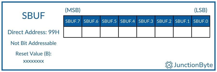
Here is an interesting point about SBUF. It may seem that there is only one register (SBUF) for holding both the outgoing and incoming data. After all, there is only one name and address (SBUF – 99H).
However, internally there are two separate registers; one acts as a transmit buffer while the other is a receive buffer. Depending on the operation, the 8051 Microcontroller automatically selects the appropriate register even though we are calling them with the same name.

- While Transmitting Data: When software writes a byte to SBUF, the 8051 automatically starts transmission. The TXD pin sends data from the transmit buffer bit-by-bit to the external device. Once the transmission is complete, the TI flag is set and we can send the next.
- While Receiving Data: When data arrives at the RXD pin, the SBUF register temporarily holds it. After it receives a complete byte, the RI flag is set. When the software tries to read the data from the SBUF, the 8051 automatically selects the receive buffer. After reading, software must clear the RI flag to accept new data.
SCON
The Serial Port Control or SCON Register configures and manages the serial communication in the 8051 Microcontroller. We can set the serial port operating mode as well as monitor the serial communication interrupts.
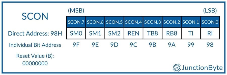
| Symbol | Description |
| SM0 | Serial Port Mode Selection Bit 0 |
| SM1 | Serial Port Mode Selection Bit 1 |
| SM2 | Multiprocessor Communication Bit. Set or Clear to Enable/Disable Multiprocessor Communication Feature in Modes 2 and 3. In Mode 2 and 3, if SM2 = 1, RI will be set only if bit 9 (RE8) is 1. In Mode 2 and 3, if SM2 = 0, RI will be set for any value of bit 9. In Mode 1, if SM2=1, RI will be set only if there is a valid stop bit. In Mode 1, if SM2=0, RI will be set with any stop bit. |
| REN | REN =1 Enable Serial Reception REN = 0 Disable Serial Reception |
| TB8 | Transmit Bit 8. The 9th Bit that will be transmitted in Modes 2 and 3 |
| RB8 | Receive Bit 8. The 9th Bit that is received in Modes 2 and 3.In Mode 1, it is the Stop Bit. |
| TI | Transmit Interrupt Flag. Set by hardware at the end of Transmission. Software must clear it |
| RI | Receive Interrupt Flag. Set by hardware at the end of Reception. Software must clear it |
SM0 and SM1
The SM0 and SM1 bits specify the Serial Port Mode of the 8051 Microcontroller as follows:
| SM0 | SM1 | Mode | Description | Baud Rate |
| 0 | 0 | 0 | 8-Bit Synchronous Shift Register Mode | Fixed Baud Rate (Baud Rate = FOSC/12) |
| 0 | 1 | 1 | Standard 8-Bit UART Mode | Variable Baud Rate (Can be set by Timer 1) |
| 1 | 0 | 2 | 9-Bit UART Mode (support for Multiprocessor Communication) | Fixed Baud Rate (Baud Rate = FOSC/32 or FOSC/64) |
| 1 | 1 | 3 | 9-Bit UART Mode (support for Multiprocessor Communication) | Variable Baud Rate (Can be set by Timer 1) |
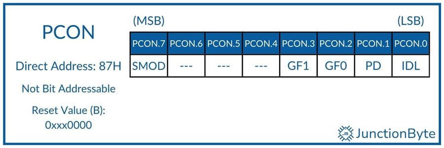
PCON
If you remember the 8051 Microcontroller Special Function Registers guide, we saw the PCON SFR has a bit for essentially doubling the baud rate generated by Timer 1. It is the SMOD bit (Bit 7 of PCON Register). If we set this bit (SMOD = 1), then the baud rate from Timer 1 doubles in Serial Communication Modes 1, 2, and 3.
8051 Microcontroller UART Modes
The 8051 microcontroller supports four serial communication modes, which we can select using the SM0 and SM1 bits of the SCON register.
Mode 0: Synchronous Shift Register Mode
In Mode 0, the 8051 Microcontroller Serial Port operates in Synchronous Mode. In this mode, the TXD pin generates a clock signal, while the RXD pin handles both transmission and reception. This mode is also known as Clocked or Synchronous Shift Register Mode and supports only a half-duplex data exchange.
The system transmits and receives data at a fixed baud rate determined by the system clock. This mode operates at one-twelfth of the system clock frequency (Fosc ÷ 12). It transmits eight bits per frame without start or stop bits.
Mode 0 works well for short-distance communication between microcontrollers or peripherals that support synchronous data transfer.
Mode 1: 8-bit UART with Variable Baud Rate
The UART Mode 1 in 8051 Microcontroller supports asynchronous communication with an 8-bit data frame (with LSB first), one start bit (always 0), and one stop bit (always 1).
We can set the baud rate through the application so that we can use it to communicate with different devices. The Timer 1 register controls the baud rate. I will show the Baud Rate calculation for Mode 1 in the next section.
During transmission, the microcontroller loads the data into the SBUF register. It automatically appends the START and STOP bits to the 8-bit data to form a 10-bit frame. After converting the parallel data to serial, the UART hardware transmits the 10-bit serial data through the TXD Pin.
The order is: Start bit, LSB……MSB, Stop bit. After transmitting the 10-bit frame, the UART will set the TI flag to indicate that SBUF is empty and it is ready for the next transmission.
For reception, the REN bit in the SCON register must be 1. If this is satisfied, then reception begins when the UART detects a high to low transition (i.e., the Start bit) on the RXD pin. The UART will load the received data into the SBUF register and it will automatically strip the Start bit and store the Stop bit in RE8.
Note that the SBUF register is loaded with received data only if the RI flag is 0 (indicating that previous data is read by software) and SM2 = 0 or Stop Bit = 1.
Most applications use Mode 1 because it supports full-duplex communication i.e., it can send and receive data simultaneously.
Mode 2: 9-bit UART with Fixed Baud Rate
The UART Mode 2 operates like Mode 1 but uses a 9-bit data format. In Mode 2, we transmit and receive 11 bits: one start bit (always 0), eight data bits (with LSB first), a ninth programmable bit, and one stop bit (always 1).
When transmitting, the ninth bit comes from the TB8 bit of the SCON register. Similarly, when receiving, the ninth bit is stored in the RB8 bit of the SCON register.
The rest of the operation is similar to Mode 1. During transmission, the UART hardware takes the 8-bit data from the SBUF register and forms a 11-bit data frame as follows: Start bit, LSB……MSB, 9th bit (TB8), Stop Bit. After transmitting this data through the TXD pin, it will automatically set the TI flag.
During reception, the REN bit must be 1. The data reception begins with the start bit (high to low transition on the RXD pin). UART will receive the data and checks if RI = 0 and SM2 = 0 (or 9th data bit is 1). If these conditions are met, then UART will store the 8 data bits in the SBUF register and the 9th bit in the RB8 bit of the SCON register.
UART Mode 2 uses a fixed baud rate. If the SMOD Bit of the PCON register is 0, the baud rate is one-sixty-fourth of the system clock frequency (Fosc ÷ 64). It is one-thirty-second of the system clock frequency (Fosc ÷ 32) if SMOD = 1.
Multiprocessor Communication
One of the important applications of the 8051 Microcontroller UART Mode 2 is Multiprocessor Communication, where multiple microcontrollers (two or more) can communicate on a shared serial bus. This is possible by setting the SM2 bit of the SCON register.
From the previous SCON register explanation, we saw that if SM2 = 1, then the RI flag will be set only if the 9th bit (RB8) = 1. Let us see how this helps in multiprocessor communication.
Assume you have one primary controller and two secondary controllers. The secondary controllers have unique identification data that is shared with the primary.
Initially, the SM2 bits of all the secondary controllers are set to 1. By transmitting 9th bit as 1, the primary can transmit the identification byte to both the secondary controllers.
Since only one of the secondary controllers will have the exact identification byte, it will recognize the received byte and makes its SM2 bit low.
Now, the primary will make the 9th bit 0 and transmit the necessary data. Only the secondary controller with its SM2 bit as 0 will receive this data. After that, it will set the SM2 bit to 1 so that it can receive another command from the primary.
This way, UART Mode 2 can facilitate multiprocessor communication.
Mode 3: 9-bit UART with Variable Baud Rate
The operation of the 8051 Microcontroller UART Mode 3 is identical to that of the Mode 2. The only difference is that Mode 3 supports a programmable baud rate.
Like Mode 2, it supports 9-bit data frames, but it uses Timer 1 to generate the baud rate instead of relying on a fixed system clock division.
8051 Microcontroller UART Baud Rate
I have been talking about Baud Rate a lot in the previous section. Let me explain more about baud rate and how to configure Timer 1 to get our desired baud rate for serial communication.
Microcontrollers need precise timing for serial data transmission and reception. The baud rate determines how fast data transfers between two devices using serial communication.
Baud rate represents the number of signal changes per second in a communication system. In UART communication, the baud rate defines how many bits transfer every second. Some standard baud rates are: 1200, 2400, 4800, 9600, 19200, and 38400 bps.
While we use bits per second or bps to represent baud rate, it is not always equal to the number of transmitted characters per second. The more appropriate unit will be symbols or characters per second.
We know that each character includes start, data, parity (optional), and stop bits. A common 8N1 format (8 data bits, no parity, 1 stop bit) requires 10 bits to transmit one character. A system operating at 9600 baud with this format can send 960 characters per second.
Importance of 11.0592 MHz in 8051 Microcontroller
We know that one machine cycle of the 8051 microcontroller is equal to 12 clock cycles. So, the machine cycle frequency is equal to Fosc ÷ 12. With a crystal frequency of 11.0592 MHz, the machine cycle frequency is 11.0592 MHz ÷ 12 = 921.6 kHz.
Coming to the UART module, it further divides the machine cycle frequency by 32 if the SMOD bit of PCON register is 0 or by 16 if the SMOD bit of PCON register is 1.
Let us consider SMOD=0 for now. This will result in a UART frequency of 921.6 KHz ÷ 32 = 28,800 Hz.
We can easily divide this number with integers and get all the standard baud rates very easily.
- 28800 ÷ 24 = 1200
- 28800 ÷ 6 = 4800
- 28800 ÷ 3 = 9600
This ease of generation of baud rate for serial communication is one of the main reasons why the peculiar 11.0592 MHz crystal frequency became popular.
Using Timer 1 for Baud Rate Generation
The Timer module essentially divides its input clock by the value loaded in its registers. We can use this feature to generate the desired baud rate for serial communication.
First, if we set the UART in Mode 1 or 3, it will automatically supply the clock to the Timer 1 with a frequency of 28,800 Hz. Next, we need to configure the Timer 1 in Mode 2 i.e., Auto Reload Mode.
If the Timer counts 3 times, it will divide the clock by 3 (28800 ÷ 3 = 9600).
Now, what should be the value in the TH1 register so that the Timer 1 overflows after 3 counts? If you remember the 8051 Microcontroller Timer guide, we can calculate the value of TH1 as 255 – Count + 1.
We already know the count as 3. So, the value in TH1 = 253 = FDH.
If all this calculation is difficult to understand, I have a simple formula that will help you set the Baud Rate for Serial Communication using Timer 1 in Mode 2.
TH1 = 256 – [(FOSC × 2SMOD) ÷ (12 × 32 × BAUD)]
The following table lists out some of the popular Baud Rates and the corresponding TH1 data for both 11.0592 MHz and 12 MHz.
| Baud Rate | Value in TH1 for FOSC | SMOD | |
| 11.0592 MHz | 12 MHz | ||
| 1200 | E8H | E6H | 0 |
| 2400 | F4H | F3H | 0 |
| 4800 | FAH | — | 0 |
| 4800 | — | F3H | 1 |
| 9600 | FDH | 0 | |
| 19200 | FDH | 1 | |
Steps to Program 8051 for Serial Communication (UART)
Steps to Initialize UART
- Select Serial Communication Mode: The SCON (Serial Control) register determines the serial communication mode. We must configure this register to set the appropriate mode. Most applications use Mode 1 (8-bit UART with variable baud rate) for reliable communication.
- Set the Baud Rate: The TH1 register and Timer 1 control the baud rate. So, we have to set Timer 1 to Mode 2 (8-bit auto-reload) and load a value in the TH1 register based on the Baud Rate calculations mentioned in the previous section.
- Enable Timer 1: The TCON (Timer Control) register starts Timer 1 by setting the TR1 (Timer 1 Run) bit to 1.
- Enable Serial Reception: Next, we have to set the REN (Receive Enable) bit in the SCON register for the microcontroller to receive serial data. Without this setting, the system will not process incoming information.
- Initialize Interrupt Flags: Finally, we have to clear the TI (Transmit Interrupt) and RI (Receive Interrupt) flags so that the system can detect new transmissions and receptions. The software must reset these flags after processing data.
Writing Data to UART (Transmitting Data)
- Load the Data into SBUF: Write a byte of data to the SBUF register. The 8051 will automatically start the transmission process. It will add appropriate Start and Stop bits and shifts the bits out sequentially.
- Wait for Transmission Completion: The TI flag in the SCON register signals when transmission finishes. The software must monitor this flag before sending the next byte.
- Clear the TI Flag: After successful transmission, we have to clear the TI flag so that the system can process the next transmission. The software resets this flag using TI = 0.
Reading Data from UART (Receiving Data)
- Wait for Incoming Data: The RI flag indicates when a byte arrives at the RXD pin. The software must check this flag continuously.
- Read the Data from SBUF: Once the RI flag is set, the system reads the received byte from SBUF. This data can then be processed.
Clear the RI Flag: After reading the data from SBUF, we have to reset the RI flag so that the microcontroller receives new data. The software clears this flag using RI = 0.
8051 Microcontroller UART Demo Code
#include <reg52.h>
void uart_init()
{
  TMOD = 0x20;  /* Timer 1, Mode 2 (8-bit auto-reload) */
  TH1 = 0xFD;   /* Baud rate 9600 */
  SCON = 0x50;  /* Mode 1, 8-bit UART, Receive Enabled */
  TR1 = 1;  	/* Start Timer 1 */
}
void uart_transmit(unsigned char data)
{
  SBUF = data;  /* Load data into buffer */
  while (TI == 0);  /* Wait for transmission to complete */
  TI = 0;  /* Clear Transmit Interrupt flag */
}
unsigned char uart_receive()
{
  while (RI == 0);  /* Wait for reception to complete */
  RI = 0;  /* Clear Receive Interrupt flag */
  return SBUF;  /* Return received byte */
}
void main()
{
  uart_init();  /* Initialize UART */
  uart_transmit('A');  /* Transmit character 'A' */
  while (1)
  {
    unsigned char received_data = uart_receive();  /* Wait for received data */
    uart_transmit(received_data);  /* Echo received data */
  }
}
Interfacing 8051 with External Devices Using UART
With proper wiring and hardware, you can connect/interface the 8051 microcontroller with external devices/systems and transfer data over UART.
Connecting 8051 to a PC via RS232
Old school computers and special industrial systems still communicate over RS232 (through a DB Connector). The 8051 microcontroller operates on TTL logic (0V for LOW and 5V for HIGH), while RS232 signals use ±12V levels. Directly connecting these signals can damage the microcontroller, so a MAX232 level converter is necessary.
Here are the hardware connections you need to follow:
- Connect TXD (Pin 11 of 8051) to T1IN (Pin 11 of MAX232).
- Connect RXD (Pin 10 of 8051) to R1OUT (Pin 12 of MAX232).
- Link T1OUT (Pin 14 of MAX232) to RX of the PC’s DB9 connector.
- Connect R1IN (Pin 13 of MAX232) to TX of the DB9 connector.
- Attach four 10µF capacitors between the MAX232 charge pump pins for voltage regulation.
Using a USB-to-Serial Converter
Modern computers lack RS232 ports. You need a USB-to-Serial converter to enable the connection between a PC and the 8051 microcontroller. This device converts USB signals into TTL or RS232 levels and vice-versa.
Some of the popular USB-to Serial Converter ICs are: PL2303, CH340, FT232RL, and CP2102.
You can easily get ready-made modules online or at local electronics stores. Check if the converter module supports 3.3V or 5V TTL levels to match the 8051 microcontroller.
- Connect the TX pin of the converter to the RXD pin of the 8051.
- Connect the RX pin of the converter to the TXD pin of the 8051.
- Attach the GND of both devices to establish a common reference.
You might have to install device specific USB drivers on the computer for these modules to work properly.
After installing the drivers you can test the communication. Open a serial monitor application (PuTTY, Tera Term, Real Term, etc.) and set the correct baud rate.
Transmit a test message from the 8051 microcontroller and verify the response on the PC.
Interfacing 8051 with Other Microcontrollers Using UART
You can configure multiple microcontrollers to exchange data through UART. The 8051 can communicate with other controllers, such as AVR, PIC, and ARM-based microcontrollers, using a simple TX-RX connection.
- Connect TXD of the first microcontroller to RXD of the second.
- Link RXD of the first microcontroller to TXD of the second.
- Share a common GND between both devices.
Both microcontrollers must use the same baud rate to avoid data loss. Use a simple handshake mechanism in software where one device sends data and waits for an acknowledgment.