One of the core features of the 8051 Microcontroller is the Timer/Counter. Timers help in applications that need precise delays, event counting, or frequency measurement. The ‘Timer’ block enables the microcontroller to manage a variety of time-dependent tasks without requiring additional external hardware. A timer operates based on an internal clock, while a counter works by tracking external input signals.
In embedded systems, one of the basic functions of timers is to generate time delays between events. A timer can control how long a motor runs or how often an LED blinks. We can use timers to generate periodic interrupts that help with regular tasks like polling sensors or refreshing displays.
Similarly, a counter can monitor external events, such as counting the number of objects passing on a conveyor belt.
Timers can also control the timing of signals in communication systems, like pulse width modulation (PWM) used to control motors or adjust light intensity.
In this guide, I will explain everything you need to know about 8051 Microcontroller Timers. I will discuss the basics of 8051 Microcontroller Timer/Counter, timer-related SFRs, different modes of Timers, and sample codes for using Timers.
While this topic is fairly independent, it would be better if you have some basic knowledge about the 8051 Microcontroller Architecture and the 8051 Microcontroller Special Function Registers (SFRs).
What is the Need for a Timer?
If you remember the previous guides on 8051 Microcontroller, I have been using a software-based delay in the application code. In this delay function, the microcontroller does nothing useful but iterates through a lengthy loop just to waste time.
This is a bad practice in critical applications where the microcontroller can do something important rather than spend its precious time/computational power going through a useless loop.
This is where Timers come into play. Instead of a software loop for generating time delay, we can use the hardware inside the microcontroller to generate pretty accurate time delays while the microcontroller can continue executing important tasks.
We know that the clock and oscillator circuit of the 8051 Microcontroller is responsible for generating the necessary clock signal for all the operations. The advantage of the clock signal generated by the oscillator circuit is it is very stable, predictable, and the most important one is it has a fixed and known time period.
If we want to measure the time period between any two events, then the simplest and accurate way is to count the number of clock pulses between the said events. This is what exactly the Timer/Counter of the 8051 Microcontroller does.
The value of the Timer Register increments for every clock pulse. Once the register is full (maximum value), the value overflows and the ‘Timer’ module interrupts the microcontroller. The microcontroller uses this interrupt as an indication of the time elapsed and takes appropriate action.
Timer vs. Counter
I have been using the terms Timer and Counter together. The reason is simple; they are essentially the same thing with the only difference being the source of pulses.
A ‘Timer’ counts the clock pulses from the internal clock/oscillator circuit while a ‘Counter’ counts the pulses from an external source (typically on the T0 and T1 pins).
When we use the Timer block as a ‘Timer,’ it acts as an Interval Timer as we can precisely calculate the time difference between two events. How is this possible?
The 8051 Microcontroller Timer has a frequency of 1/12th of the frequency of the oscillator. This is due to the fact that the timer registers increment once every machine cycle. In the case of a standard 8051 Microcontroller, one machine cycle corresponds to 12 clock cycles. Hence, the timer update rate is FOSC ÷ 12.
If the 8051 Microcontroller has a 12 MHz crystal, then the Timer frequency is 12 MHz ÷ 12 = 1 MHz and the period is 1 ÷ 1 MHz = 1µs.
But the 11.0592 MHz crystal is pretty standard (it has something to do with the baud rate for serial communication and we will see why in the 8051 Microcontroller Serial Communication guide).
In this case, the Timer frequency is 11.0592 MHz ÷ 12 = 921.6 kHz and the period is 1 ÷ 921.6 kHz = 1.085µs.
Alternatively, we can also use the Timer block as a ‘Counter’ where it counts the pulses from an external source. Since the frequency of the external pulses is unknown, we cannot use this as a timer but rather an event counter.
Overview of Timers/Counters in 8051 Microcontroller
The original 8051 Microcontroller has two 16-bit Timers, Timer 0 and Timer 1. These can independently act as either an interval timer or event counter. The 8052 Microcontroller adds another Timer module, Timer 2 in addition to these two.
Timer 0 and Timer 1 are almost identical in their basic structure with similar operational modes and configurations (we will take a look at these later). Both timers can act as a timer (driven by the internal clock) or as a counter (triggered by external signals).
Timer 2, however, has some advanced capabilities, such as auto-reload functionality and the ability to operate in capture mode. These features make Timer 2 suitable for tasks like frequency measurement and serial communication support (baud rate generation).
Since Timer 2 is slightly advanced compared to Timer 0 and Timer 1, I will make a dedicated guide on 8051 Microcontroller Timer 2 and focus this guide on the two essential timer modules (Timer 0 and Timer 1).
Timer Registers
We have already seen the Timer-related registers in the 8051 Microcontroller Special Function Registers guide. However, here’s a detailed overview of all the Timer Registers in the 8051 Microcontroller.
THx/TLx
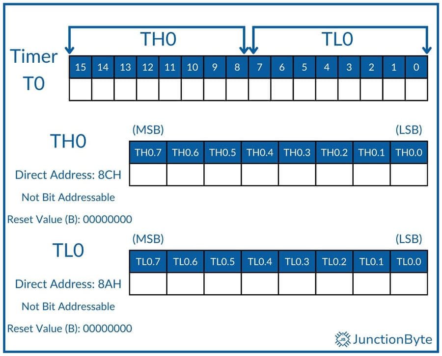
As I said before, both Timer 0 and Timer 1 of the 8051 Microcontroller are 16-bit timers. To hold the value of the count, both these timers have two 8-bit registers each. Timer 0 has TL0 (Timer 0 Lower Byte) and TH0 (Timer 0 Higher Byte) that work as individual 8-bit registers or collectively as a 16-bit register. Note that there is no special 16-bit register. We have to use these two 8-bit registers to work together and form the 16-bit data.
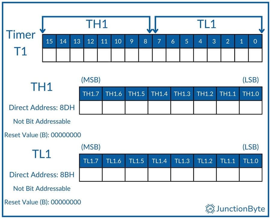
Likewise, Timer 1 has TL1 (Timer 1 Lower Byte) and TH1 (Timer 1 Higher Byte) registers.
TCON
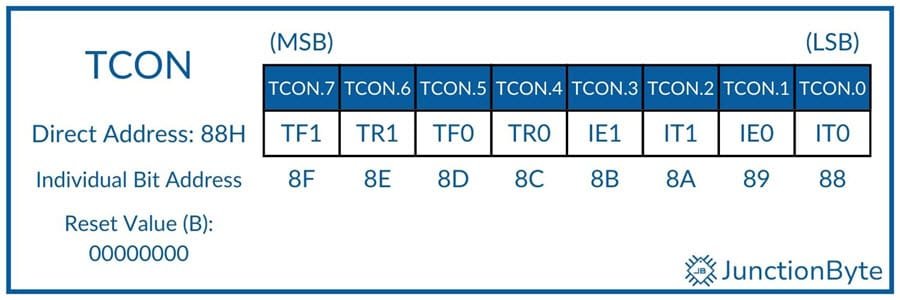
The Timer/Counter Control or TCON register consists of the bits for starting or stopping the Timers as well as the overflow flags for both the timers. Additionally, the TCON register also has bits for configuring the external interrupts.
| Bit | Name | Description |
| TF1 | Timer 1 Overflow Flag | Set by hardware when Timer/Counter 1 Overflows. Can be cleared through software. Automatically cleared by hardware when the CPU executes an Timer 1 ISR at 001BH. |
| TR1 | Timer 1 Run Control Bit | TR1=1, Start Timer/Counter 1 TR1=0, Stops Timer/Counter 1 |
| TF0 | Timer 0 Overflow Flag | Set by hardware when Timer/Counter 0 Overflows. Can be cleared through software. Automatically cleared by hardware when the CPU executes an Timer 0 ISR at 000BH. |
| TR0 | Timer 0 Run Control Bit | TR0=1, Start Timer/Counter 0 TR0=0, Stops Timer/Counter 0 |
| IE1 | External Interrupt 1 Edge Detect Flag | Set by hardware when it detects an external interrupt on INT1 – P3.3. Automatically cleared by hardware when the CPU executes Interrupt 1 ISR (at 0013H) only if it is an edge-triggered interrupt. |
| IT1 | External Interrupt 1 Type Control Bit | IT1=1, INT1 is an Edge Triggered Interrupt (Falling Edge) IT1=0, INT1 is a Level Triggered Interrupt (Low Level) |
| IE0 | External Interrupt 0 Edge Detect Flag | Set by hardware when it detects an external interrupt on INT0 – P3.2. Automatically cleared by hardware when the CPU executes Interrupt 0 ISR (at 0003H) only if it is an edge-triggered interrupt. |
| IT0 | External Interrupt 0 Type Control Bit | IT0=1, INT0 is an Edge Triggered Interrupt (Falling Edge) IT0=0, INT0 is a Level Triggered Interrupt (Low Level) |
We can configure the Timers to operate either in Polling mode or Interrupt mode. In polling mode, the microcontroller continuously monitors the overflow flag (TF0 in case of Timer 0 and TF1 in case of Timer 1) to see if the set time has elapsed. This wastes CPU cycles.
Alternatively, the interrupt mode lets the microcontroller do some other work and automatically interrupts if an overflow occurs.
TMOD
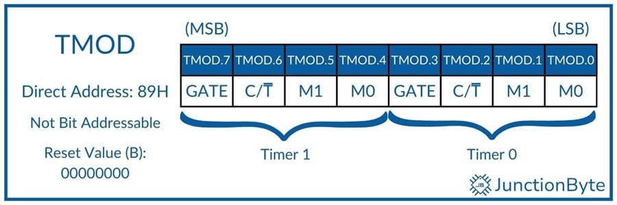
The Timer/Counter Mode Control or TMOD register helps in selecting the mode of the Timers 0 and 1. The lower four bits control Timer 0 while the higher four bits control Timer 1.
| Symbol | Description |
| GATE | OR Gate Enable Bit for Timer 1. Enable software or hardware control of the Timer |
| C/T | Set Timer 1 as Event Counter or Interval Timer |
| M1 | Timer/Counter Operating Mode Select Bit 1 for Timer 1 |
| M0 | Timer/Counter Operating Mode Select Bit 0 for Timer 1 |
| GATE | OR Gate Enable Bit for Timer 0. Enable software or hardware control of the Timer |
| C/T | Set Timer 0 as Event Counter or Interval Timer |
| M1 | Timer/Counter Operating Mode Select Bit 1 for Timer 0 |
| M0 | Timer/Counter Operating Mode Select Bit 0 for Timer 0 |
Gate
When Gate=0, only the TR0 (or TR1) bit controls the start/stop action of the Timer 0 (or Timer 1). Since we typically configure the TR0 or TR1 bits in the application, this method is known as ‘Software Control’ of the Timer/Counter.
If we make the Gate=1, then INT0 (or INT1) along with TR0 (or TR1) controls the start stop action of the Timer 0 (or Timer 1). Since INT0 or INT1 are out of bounds of the software, this method is commonly known as ‘Hardware Control’ of the Timer/Counter.
You can understand this better if you look at the block diagram of the Timer Module.
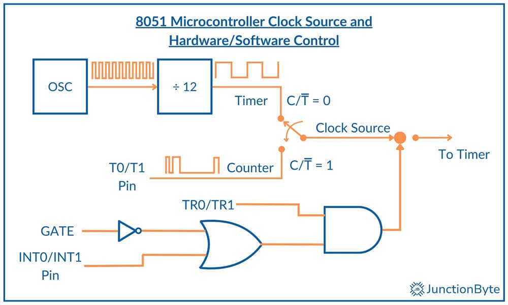
Here, the ‘Gate’ bit controls a NOT gate and thereby enables or disables the OR gate.
C/T
If you look at the above block diagram, then the C/T bit configures the clock source for the Timer/Counter. If C/T=0, then the clock source for the Timer is the Internal Clock generated by the oscillator circuit (after dividing it by 12). Hence, this mode configures the Timer/Counter as Interval Timer. We can use this to calculate the time between two events or to generate a delay.
When C/T=1, the clock source is connected to the Timer Input Pins (T0 – P3.4 for Timer 0 and T1 – P3.5 for Timer 1). In this case, the Timer/Counter counts the external pulses and hence it acts as an Event Counter.
M1 and M0
The M0 and M1 bits of the TMOD Register set the Timer Mode. Timers in 8051 Microcontrollers have four modes of operation. Both the Timers (Timer 0 and Timer 1) have the same set of operating modes.
| M1 | M0 | Mode | Description |
| 0 | 0 | 0 | 13-Bit Timer Mode (THx is 8-Bit Timer with TLx as 5-bit Prescaler) |
| 0 | 1 | 1 | 16-Bit Timer Mode (THx and TLx are cascaded, no prescaler) |
| 1 | 0 | 2 | 8-Bit Auto-reload Timer/Counter (when TLx overflows, it is loaded with value in THx) |
| 1 | 1 | 3 | Split Timer Mode (two 8-Bit Timers). TL0 and TH0 are two timers/counters that are controlled by Timer 0 and Timer 1 control bits. Timer 1 is disabled (holds its count) |
Operating Modes of 8051 Microcontroller Timer/Counter
Mode 1
We will first learn Mode 1 and then look at Mode 0 (as Mode 0 is essentially a subset of Mode 1).
In Mode 1, the Timer of the 8051 Microcontroller acts as a 16-bit Timer/Counter. As a result, you can load values in the range of 0000H to FFFFH in the TLx and THx registers (x=0 for Timer 0 and X=1 for Timer 1).
After loading the registers with the initial value, we can start the Timer. It will increment the value for every Timer Clock Pulse (Oscillator Frequency ÷ 12). Once the value reaches all 1’s i.e., FFFFH (65,535), then contents of the registers become 0000H and the Timer module generates the Timer Interrupt (sets the corresponding Overflow Flag, TF0 – Timer 0 and TF1 – Timer 1).
How to Calculate Initial Value to be Loaded in Timer Registers?
Assume you want to generate a delay of 1 ms using the Timer. With an oscillator frequency of 11.0592 MHz, what is the initial value that must be loaded to the Timer Registers (TLx and THx)?
We know that the Timer Clock Frequency = Oscillator Frequency ÷ 12
Timer Clock Frequency = 11.0592 MHz ÷ 12 = 921.6 kHz.
The Timer Clock Period = 1 ÷ Timer Clock Frequency = 1 ÷ 921.6 KHz = 1.085 µs.
This means, the value in the timer registers in incremented every Timer Clock Pulse i.e., 1.085 µs.
If one clock pulse is 1.085 µs, then how many clock pulses make 1 ms? We simply have to divide 1 ms by 1.085 µs to get the total number of Timer Clock Pulses needed to generate a delay of 1 ms.
Therefore, the number of timer clock pulses to generate 1 ms delay = 1 ms ÷ 1.085 µs = 921.6 (rounding it off to 922).
This means that after 922 timer clock pulses, the timer should overflow. So, the initial value that we must load into the Timer registers is:
Initial Value (or Reload Value) = 65535 – 922 + 1 = 64614. In hexadecimal, 64614 = FC66H. The extra +1 is necessary for the Timer to overflow from FFFFH to 0000H.
This is the value that must be loaded into the Timer Registers. The lower byte goes into TLx while the higher byte goes into THx. THx = FCH and TLx = 66H.
Mode 0
Timer Mode 0 is very similar to Timer Mode 1. The only difference is it is a 13-bit counter rather than a 16-bit counter. Hence, when the count reaches 8191 (1FFFFH), which is the maximum for a 13-bit counter, the Timer rolls over to 0000H and generates the Timer interrupt.
Let us take the same example of generating 1 ms delay with a 11.0592 MHz crystal frequency. Here’s how you can calculate the initial values for Timer Registers in order to configure in Mode 0.
The count remains the same i.e., 922. Since the maximum value now is 8191, the initial value must be 8191 – 922 + 1 = 7270 or 1C66H. Here comes the interesting part on the actual values that go into the THx and TLx registers.
Let me rewrite 1C66H in binary as 0001 1100 0110 0110 b.
The lower 5 bits i.e., 00110 b or 06H must go into TLx and the next higher 8 bits i.e., 1110 0011 b or E3H must go into THx to generate a delay of 1 ms using Timer in Mode 0.
Mode 2
Timer Mode 2 is an 8-bit Timer. It uses only the TLx register to count the value. The THx register holds the value that must be loaded into the TLx register. When the TLx overflows from FFH to 00H, the value in the THx register is automatically loaded into the TLx register. Hence, Timer Mode 2 is also known as Auto-Reload Timer Mode.
Where is this useful? Before that, we need to look at the problem with Timer Mode 0 and Timer Mode 1. Even though we calculate the initial values to generate a time delay, the generated time delay will not be accurate as we ignored the rounding of the fractional number to integer and importantly the overhead of clearing and loading the registers (THx, TLx, TRx, TFx). This process takes some CPU resources and we are ignoring a small number of machine cycles to execute these instructions.
Timer Mode 2 tries to reduce this overhead (to some extent) by automatically reloading the TLx register immediately after it overflows. We will see how to properly use Timer Mode 2 in Serial Communication (UART).
Since it is an 8-bit counter, the maximum value you can load is only 255. For example, if you want to generate a square wave with a period of 500 µs (with 50% duty cycle, on time is 250 µs and off time is 250 µs), here’s the value of the THx register:
As usual, we will assume the crystal frequency as 11.0592 MHz. So, the Timer Clock Period is still 1.085 µs.
In order to generate a delay of 250 µs (which essentially generates a square wave with a period of 500 µs), the count is 250µs ÷ 1.085µs = 230.4. Rounding it off to 230.
The value that goes into THx is 255 – 230 + 1 = 26 or 1AH.
Mode 3
For the previous three modes, we can configure both Timer 0 and Timer 1 independently to work in either Mode 0, Mode 1, or Mode 2. However, things are somewhat different in Mode 3.
First of all, we can configure only Timer 0 in Mode 3. Yes. We will be using registers of Timer 1 as well but all the counting action happens only in TL0 and TH0 registers. The Timer Mode 3 consists of two independent 8-bit timers.
Timer 0 control bits (TR0, GATE0, C/T0, INT0, and TF0) control the TL0 register while Timer 1 control bits (TR1, GATE1, C/T1, INT1, and TF1) control the TH0 register. We cannot configure Timer 1 in Mode 3 (even if we do, it stops the operation and holds the count).
We can still use Timer 1 in other modes (Mode 0, Mode 1, or Mode 2) as long as you don’t use the Timer 1 interrupt (as TF1 is used by the TH0 register).
8051 Microcontroller Timer Code Examples
Generate 1 ms Delay using Timer 0 Mode 0 (Fosc = 11.0592 MHz)
/* Include the 8051 Header File */
#include <reg52.h>
/* Set a Test Pin. Pin 0 of Port 2 */
sbit testPIN = P2^0;
/* Timer 0 Delay Function Prototype */
void timer0_delay();

void main()
{
  TMOD = 0x00; /* Timer 0 Mode 0 (13-bit Timer Mode) */
  while(1)
  {
    testPIN = ~testPIN; /* Toggle the Test Pin */
    timer0_delay();    	/* Call the Delay Function */
  }
}

/* Timer 0 Delay Function Definition */
void timer0_delay()
{
  /* Load Initial Value in the Timer Register
   * 8-bit value in TH0 and 5-bit value in TL0 */
  TH0 = 0xE3;
  TL0 = 0x06;
  TR0 = 1;        	/* Start the Timer 0 */
  /* Wait until Timer 0 overflows
   *  We can check for overflow flag set */
  while(TF0 == 0);
  TR0 = 0;        	/* Stop Timer 0 */
  TF0 = 0;        	/* Clear Timer 0 Flag */
}
Generate a Square Wave of 2 kHz Frequency using Timer
The period of a square wave with frequency of 2 kHz = 1 ÷ 2 kHz = 0.5 ms or 500 µs.
With a 50% duty cycle, the ON duration = OFF duration = 500 µs ÷ 2 = 250 µs
So, essentially, we have to generate a delay of 250 µs. Let us use Timer 1 in Mode 1.
Timer Frequency = Fosc ÷ 12 = 11.0592 MHz ÷ 12 = 921.6 kHz
Period of Timer = 1 ÷ 921.6 kHz = 1.085 µs
In order to get a delay of 250 µs, the number of timer pulses = 250 µs ÷ 1.085 µs = 230 (rounded).
Count of Timer = 65535 – 230 + 1 = 65306 = FF1A
Value in TH1 and TL1 are: TH1 = FF, TL1 = 1A
/* Include the 8051 Header File */
# include <reg52.h>
/* Define Pin P2.0 as Square Wave Bit */
sbit squareBit = P2^0;
void main ( )
{
  /* Set Pin P2.0 to logic ‘1’ to make it Output */
  squareBit = 1;
  /* Configured Timer 1 as Timer and in Mode 1 */
  TMOD = 0x01;
  /* Repeat the following statements forever
   * to generate square wave */
  while (1)
  {
    /* Load Count in Timer Registers TH1 and TL1 */
    TH1 = 0xFF;
    TL1 = 0x1A;
    TR1 = 1; /* Start Timer 1 */
    while (TF1 = = 0); /* Wait until TF1 overflows */
    TR1 = 0; /* Stop Timer 1*/
    TF1 = 0; /* Clear Timer Overflow Flag */
    /* Toggle Pin P2.0 to get Square Wave */
    squareBit = ~ squareBit;
  }
}
Example for Timer Mode 2
With an oscillator frequency of 11.0592 MHz, let us use Timer Mode 2 to generate a Square Wave of frequency 10 kHz.
The frequency of Timer Clock = 11.0592 MHz ÷ 12 = 921.6 kHz
The period of Timer clock = 1 ÷ 921.6 kHz = 1.085 µs.
Time period of Square Wave with frequency of 10 KHz = 1 ÷ 10 kHz = 0.1 ms
ON time = OFF time = 0.1 ms ÷ 2 = 0.05 ms = 50 µs
The count to be loaded in TH0 is,
count = maximum value of Mode 2 – (pulse period / timer clock period) + 1
= 255 – (50 µs / 1.085 µs) + 1 = 256 – 46 = 210 = D2H
#include<reg52.h>
/* Define Pin P1.0 as squarePin */
sbit squarePin = P1^0;
void main()
{
  TMOD = 0x02; /* Configure Timer 0 in Mode 2 */
  TH0 = 0xD2; /* Load Count in TH0 */
  squarePin = 1; /* Set P1.0 to get ON time of wave
  TR0 = 1; /* Start Timer 0 */
  while (1) /* Repeat process forever */
  {
    while (TF0 = = 0); //* Wait until Timer 0 overflows */
    squarePin = ~ squarePin ; /* Toggle Pin P1.0 to get square wave */
    TF0 = 0; /* Clear Timer 0 Overflow Flag */
  }
}